OM13005,598 NXP Semiconductors, OM13005,598 Datasheet - Page 298
OM13005,598
Manufacturer Part Number
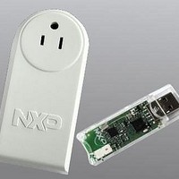
OM13005,598
Description
BOARD EVAL EM773 METER US PLUG
Manufacturer
NXP Semiconductors
Type
Other Power Managementr
Specifications of OM13005,598
Design Resources
Plug Meter Schematics, Gerber Files USB Dongle Schematics, Gerber Files
Main Purpose
Power Management, Energy/Power Meter
Embedded
Yes, MCU, 32-Bit
Utilized Ic / Part
EM773FHN33,551
Interface Type
USB
Maximum Operating Temperature
+ 150 C
Operating Supply Voltage
1.8 V to 3.6 V
Product
Power Management Development Tools
Lead Free Status / RoHS Status
Lead free / RoHS Compliant
Primary Attributes
-
Secondary Attributes
-
Lead Free Status / Rohs Status
Lead free / RoHS Compliant
For Use With/related Products
EM773, OL2381
Other names
568-6680


NXP Semiconductors
Table 100. Modem status interrupt generation . . . . . . . . .82
Table 101. UART Line Status Register (U0LSR - address
Table 102. UART Modem Status Register (U0MSR - address
Table 103. UART Scratch Pad Register (U0SCR - address
Table 104. Auto-baud Control Register (U0ACR - address
Table 105. UART Fractional Divider Register (U0FDR -
Table 106. Fractional Divider setting look-up table . . . . . .91
Table 107. UART Transmit Enable Register (U0TER -
Table 108. UART RS485 Control register (U0RS485CTRL -
Table 109. UART RS-485 Address Match register
Table 110. UART RS-485 Delay value register
Table 111. I
Table 112. Register overview: I
Table 113. I
Table 114. I
Table 115. I
Table 116. I
Table 117. I
Table 118. I
Table 119. I2SCLL + I2SCLH values for selected I
Table 120. I
Table 121. I
Table 122. I
Table 123. I
Table 124. I
Table 125. I2C0CONSET and I2C1CONSET used to
Table 126. I2C0CONSET and I2C1CONSET used to
Table 127. Abbreviations used to describe an I
Table 128. I2CONSET used to initialize Master Transmitter
Table 129. Master Transmitter mode. . . . . . . . . . . . . . . . 117
UM10415
User manual
0x4000 8014, Read Only) bit description . . . .83
0x4000 8018) bit description . . . . . . . . . . . . . .85
0x4000 8014) bit description . . . . . . . . . . . . . .85
0x4000 8020) bit description . . . . . . . . . . . . . .86
address 0x4000 8028) bit description. . . . . . . .89
address 0x4000 8030) bit description. . . . . . . .92
address 0x4000 804C) bit description . . . . . .92
(U0RS485ADRMATCH - address 0x4000 8050)
bit description . . . . . . . . . . . . . . . . . . . . . . . . . .93
(U0RS485DLY - address 0x4000 8054) bit
description . . . . . . . . . . . . . . . . . . . . . . . . . . . .93
0000)
0x4000 0000) bit description . . . . . . . . . . . . .100
description . . . . . . . . . . . . . . . . . . . . . . . . . . .102
description . . . . . . . . . . . . . . . . . . . . . . . . . . .102
0x4000 000C) bit description . . . . . . . . . . . . .103
address 0x4000 0010) bit description. . . . . . .103
0x4000 0014) bit description . . . . . . . . . . . . .103
values . . . . . . . . . . . . . . . . . . . . . . . . . . . . . . .104
0x4000 0018) bit description . . . . . . . . . . . . .104
- 0x4000 001C) bit description . . . . . . . . . . . .105
0x4000 00[20, 24, 28]) bit description . . . . . .106
0x4000 002C) bit description . . . . . . . . . . . . .107
0x4000 00[30, 34, 38, 3C]) bit description . . .107
configure Master mode . . . . . . . . . . . . . . . . . .108
configure Slave mode . . . . . . . . . . . . . . . . . . .109
115
mode. . . . . . . . . . . . . . . . . . . . . . . . . . . . . . . . 115
2
2
2
2
2
2
2
2
2
2
2
2
C-bus pin description . . . . . . . . . . . . . . . . . . .99
C Control Set register (I2C0CONSET - address
C Status register (I2C0STAT - 0x4000 0004) bit
C Data register (I2C0DAT - 0x4000 0008) bit
C Slave Address register 0 (I2C0ADR0-
C SCL HIGH Duty Cycle register (I2C0SCLH -
C SCL Low duty cycle register (I2C0SCLL -
C Control Clear register (I2C0CONCLR -
C Monitor mode control register (I2C0MMCTRL
C Slave Address registers (I2C0ADR[1, 2, 3]-
C Data buffer register (I2C0DATA_BUFFER -
C Mask registers (I2C0MASK[0, 1, 2, 3] -
. . . . . . . . . . . . . . . . . . . . . . . . . . . . . . .99
2
C (base address 0x4000
All information provided in this document is subject to legal disclaimers.
2
C operation.
Rev. 1 — 10 September 2010
2
C clock
Table 130. Master Receiver mode . . . . . . . . . . . . . . . . . 120
Table 131. I2C0ADR and I2C1ADR usage in Slave Receiver
Table 132. I2C0CONSET and I2C1CONSET used to
Table 133. Slave Receiver mode . . . . . . . . . . . . . . . . . 123
Table 134. Slave Transmitter mode . . . . . . . . . . . . . . . . 127
Table 135. Miscellaneous States . . . . . . . . . . . . . . . . . . 129
Table 136. SPI pin descriptions . . . . . . . . . . . . . . . . . . . 141
Table 137. Register overview: SPI0 (base address 0x4004
Table 138: SPI/SSP Control Register 0 (SSP0CR0 - address
Table 139: SPI/SSP Control Register 1 (SSP0CR1 - address
Table 140: SPI/SSP Data Register (SSP0DR - address
Table 141: SPI/SSP Status Register (SSP0SR - address
Table 142: SPI/SSP Clock Prescale Register (SSP0CPSR -
Table 143: SPI/SSP Interrupt Mask Set/Clear register
Table 144: SPI/SSP Raw Interrupt Status register (SSP0RIS
Table 145: SPI/SSP Masked Interrupt Status register
Table 146: SPI/SSP interrupt Clear Register (SSP0ICR -
Table 147. Counter/timer pin description . . . . . . . . . . . . 156
Table 148. Register overview: 16-bit counter/timer 0 CT16B0
Table 149. Interrupt Register (TMR16B0IR - address
Table 150. Timer Control Register (TMR16B0TCR - address
Table 151. Match Control Register (TMR16B0MCR -
Table 152. Capture Control Register (TMR16B0CCR -
Table 153. External Match Register (TMR16B0EMR -
Table 154. External match control . . . . . . . . . . . . . . . . . 161
Table 155. Count Control Register (TMR16B0CTCR -
Table 156. PWM Control Register (TMR16B0PWMC -
Table 157. Counter/timer pin description . . . . . . . . . . . . 167
Table 158. Register overview: 32-bit counter/timer 0 CT32B0
Table 159. Register overview: 32-bit counter/timer 1 CT32B1
Table 160: Interrupt Register (TMR32B0IR - address
Chapter 21: EM773 Supplementary information
mode . . . . . . . . . . . . . . . . . . . . . . . . . . . . . . . 122
initialize Slave Receiver mode . . . . . . . . . . . . 122
0000) . . . . . . . . . . . . . . . . . . . . . . . . . . . . . . . 142
0x4004 0000) bit description . . . . . . . . . . . . . 143
0x4004 0004) bit description . . . . . . . . . . . . . 144
0x4004 0008) bit description . . . . . . . . . . . . . 145
0x4004 000C) bit description . . . . . . . . . . . . . 145
address 0x4004 0010) bit description . . . . . . 146
(SSP0IMSC - address 0x4004 0014) bit
description . . . . . . . . . . . . . . . . . . . . . . . . . . . 146
- address 0x4004 0018) bit description . . . . . 147
(SSP0MIS - address 0x4004 001C) bit description
147
address 0x4004 0020) bit description . . . . . . 148
(base address 0x4000 C000) . . . . . . . . . . . . 157
0x4000 C000) bit description . . . . . . . . . . . . . 158
0x4000 C004) bit description . . . . . . . . . . . . 158
address 0x4000 C014) bit description
address 0x4000 C028) bit description . . . . . 160
address 0x4000 C03C) bit description . . . . . 161
address 0x4000 C070) bit description . . . . . 162
address 0x4000 C074 and TMR16B1PWMC-
address 0x4001 0074) bit description . . . . . . 163
(base address 0x4001 4000) . . . . . . . . . . . . 168
(base address 0x4001 8000) . . . . . . . . . . . . 169
0x4001 4000 and TMR32B1IR - address
0x4001 8000) bit description . . . . . . . . . . . . . 169
UM10415
© NXP B.V. 2010. All rights reserved.
298 of 310
. . . . 159
Related parts for OM13005,598
Image
Part Number
Description
Manufacturer
Datasheet
Request
R

Part Number:
Description:
NXP Semiconductors designed the LPC2420/2460 microcontroller around a 16-bit/32-bitARM7TDMI-S CPU core with real-time debug interfaces that include both JTAG andembedded trace
Manufacturer:
NXP Semiconductors
Datasheet:

Part Number:
Description:
NXP Semiconductors designed the LPC2458 microcontroller around a 16-bit/32-bitARM7TDMI-S CPU core with real-time debug interfaces that include both JTAG andembedded trace
Manufacturer:
NXP Semiconductors
Datasheet:
Part Number:
Description:
NXP Semiconductors designed the LPC2468 microcontroller around a 16-bit/32-bitARM7TDMI-S CPU core with real-time debug interfaces that include both JTAG andembedded trace
Manufacturer:
NXP Semiconductors
Datasheet:
Part Number:
Description:
NXP Semiconductors designed the LPC2470 microcontroller, powered by theARM7TDMI-S core, to be a highly integrated microcontroller for a wide range ofapplications that require advanced communications and high quality graphic displays
Manufacturer:
NXP Semiconductors
Datasheet:
Part Number:
Description:
NXP Semiconductors designed the LPC2478 microcontroller, powered by theARM7TDMI-S core, to be a highly integrated microcontroller for a wide range ofapplications that require advanced communications and high quality graphic displays
Manufacturer:
NXP Semiconductors
Datasheet:
Part Number:
Description:
The Philips Semiconductors XA (eXtended Architecture) family of 16-bit single-chip microcontrollers is powerful enough to easily handle the requirements of high performance embedded applications, yet inexpensive enough to compete in the market for hi
Manufacturer:
NXP Semiconductors
Datasheet:
Part Number:
Description:
The XA-S3 device is a member of Philips Semiconductors? XA(eXtended Architecture) family of high performance 16-bitsingle-chip microcontrollers
Manufacturer:
NXP Semiconductors
Datasheet:

Part Number:
Description:
The NXP BlueStreak LH75401/LH75411 family consists of two low-cost 16/32-bit System-on-Chip (SoC) devices
Manufacturer:
NXP Semiconductors
Datasheet:
Part Number:
Description:
The NXP LPC3130/3131 combine an 180 MHz ARM926EJ-S CPU core, high-speed USB2
Manufacturer:
NXP Semiconductors
Datasheet:
Part Number:
Description:
The NXP LPC3141 combine a 270 MHz ARM926EJ-S CPU core, High-speed USB 2
Manufacturer:
NXP Semiconductors
Part Number:
Description:
The NXP LPC3143 combine a 270 MHz ARM926EJ-S CPU core, High-speed USB 2
Manufacturer:
NXP Semiconductors

Part Number:
Description:
The NXP LPC3152 combines an 180 MHz ARM926EJ-S CPU core, High-speed USB 2
Manufacturer:
NXP Semiconductors
Part Number:
Description:
The NXP LPC3154 combines an 180 MHz ARM926EJ-S CPU core, High-speed USB 2
Manufacturer:
NXP Semiconductors

Part Number:
Description:
Standard level N-channel enhancement mode Field-Effect Transistor (FET) in a plastic package using NXP High-Performance Automotive (HPA) TrenchMOS technology
Manufacturer:
NXP Semiconductors
Datasheet: