OM13005,598 NXP Semiconductors, OM13005,598 Datasheet - Page 31
OM13005,598
Manufacturer Part Number
OM13005,598
Description
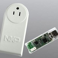
BOARD EVAL EM773 METER US PLUG
Manufacturer
NXP Semiconductors
Type
Other Power Managementr
Specifications of OM13005,598
Design Resources
Plug Meter Schematics, Gerber Files USB Dongle Schematics, Gerber Files
Main Purpose
Power Management, Energy/Power Meter
Embedded
Yes, MCU, 32-Bit
Utilized Ic / Part
EM773FHN33,551
Interface Type
USB
Maximum Operating Temperature
+ 150 C
Operating Supply Voltage
1.8 V to 3.6 V
Product
Power Management Development Tools
Lead Free Status / RoHS Status
Lead free / RoHS Compliant
Primary Attributes
-
Secondary Attributes
-
Lead Free Status / Rohs Status
Lead free / RoHS Compliant
For Use With/related Products
EM773, OL2381
Other names
568-6680


NXP Semiconductors
UM10415
User manual
3.7.1.1 Power configuration in Active mode
3.7.2.1 Power configuration in Sleep mode
3.7.2.2 Programming Sleep mode
3.7.2 Sleep mode
Power consumption in Active mode is determined by the following configuration choices:
In Sleep mode, the system clock to the ARM Cortex-M0 core is stopped, and execution of
instructions is suspended until either a reset or an interrupt occurs.
Peripheral functions, if selected to be clocked in the SYSAHBCLKCTRL register, continue
operation during Sleep mode and may generate interrupts to cause the processor to
resume execution. Sleep mode eliminates dynamic power used by the processor itself,
memory systems and related controllers, and internal buses. The processor state and
registers, peripheral registers, and internal SRAM values are maintained, and the logic
levels of the pins remain static.
Power consumption in Sleep mode is configured by the same settings as in Active mode:
The following steps must be performed to enter Sleep mode:
1. The DPDEN bit in the PCON register must be set to zero
2. The SLEEPDEEP bit in the ARM Cortex-M0 SCR register must be set to zero, see
3. Use the ARM Cortex-M0 Wait-For-Interrupt (WFI) instruction.
•
•
•
•
•
•
•
•
The SYSAHBCLKCTRL register controls which memories and peripherals are
running
The power to various analog blocks (PLL, oscillators, the BOD circuit, and the flash
block) can be controlled at any time individually through the PDRUNCFG register
(Table
The clock source for the system clock can be selected from the IRC (default), the
system oscillator, or the watchdog oscillator (see
The system clock frequency can be selected by the SYSPLLCTRL
SYSAHBCLKDIV register
Selected peripherals (UART, SPI0, WDT) use individual peripheral clocks with their
own clock dividers. The peripheral clocks can be shut down through the
corresponding clock divider registers
The clock remains running.
The system clock frequency remains the same as in Active mode, but the processor is
not clocked.
Analog and digital peripherals are selected as in Active mode.
(Table
37).
250).
(Table
All information provided in this document is subject to legal disclaimers.
17).
Rev. 1 — 10 September 2010
(Table
16).
(Table 18
Chapter 3: EM773 System configuration
to
Figure 3
Table
19).
(Table
and related registers).
43).
UM10415
© NXP B.V. 2010. All rights reserved.
(Table
6) and the
31 of 13
Related parts for OM13005,598
Image
Part Number
Description
Manufacturer
Datasheet
Request
R

Part Number:
Description:
NXP Semiconductors designed the LPC2420/2460 microcontroller around a 16-bit/32-bitARM7TDMI-S CPU core with real-time debug interfaces that include both JTAG andembedded trace
Manufacturer:
NXP Semiconductors
Datasheet:

Part Number:
Description:
NXP Semiconductors designed the LPC2458 microcontroller around a 16-bit/32-bitARM7TDMI-S CPU core with real-time debug interfaces that include both JTAG andembedded trace
Manufacturer:
NXP Semiconductors
Datasheet:
Part Number:
Description:
NXP Semiconductors designed the LPC2468 microcontroller around a 16-bit/32-bitARM7TDMI-S CPU core with real-time debug interfaces that include both JTAG andembedded trace
Manufacturer:
NXP Semiconductors
Datasheet:
Part Number:
Description:
NXP Semiconductors designed the LPC2470 microcontroller, powered by theARM7TDMI-S core, to be a highly integrated microcontroller for a wide range ofapplications that require advanced communications and high quality graphic displays
Manufacturer:
NXP Semiconductors
Datasheet:
Part Number:
Description:
NXP Semiconductors designed the LPC2478 microcontroller, powered by theARM7TDMI-S core, to be a highly integrated microcontroller for a wide range ofapplications that require advanced communications and high quality graphic displays
Manufacturer:
NXP Semiconductors
Datasheet:
Part Number:
Description:
The Philips Semiconductors XA (eXtended Architecture) family of 16-bit single-chip microcontrollers is powerful enough to easily handle the requirements of high performance embedded applications, yet inexpensive enough to compete in the market for hi
Manufacturer:
NXP Semiconductors
Datasheet:
Part Number:
Description:
The XA-S3 device is a member of Philips Semiconductors? XA(eXtended Architecture) family of high performance 16-bitsingle-chip microcontrollers
Manufacturer:
NXP Semiconductors
Datasheet:

Part Number:
Description:
The NXP BlueStreak LH75401/LH75411 family consists of two low-cost 16/32-bit System-on-Chip (SoC) devices
Manufacturer:
NXP Semiconductors
Datasheet:
Part Number:
Description:
The NXP LPC3130/3131 combine an 180 MHz ARM926EJ-S CPU core, high-speed USB2
Manufacturer:
NXP Semiconductors
Datasheet:
Part Number:
Description:
The NXP LPC3141 combine a 270 MHz ARM926EJ-S CPU core, High-speed USB 2
Manufacturer:
NXP Semiconductors
Part Number:
Description:
The NXP LPC3143 combine a 270 MHz ARM926EJ-S CPU core, High-speed USB 2
Manufacturer:
NXP Semiconductors

Part Number:
Description:
The NXP LPC3152 combines an 180 MHz ARM926EJ-S CPU core, High-speed USB 2
Manufacturer:
NXP Semiconductors
Part Number:
Description:
The NXP LPC3154 combines an 180 MHz ARM926EJ-S CPU core, High-speed USB 2
Manufacturer:
NXP Semiconductors

Part Number:
Description:
Standard level N-channel enhancement mode Field-Effect Transistor (FET) in a plastic package using NXP High-Performance Automotive (HPA) TrenchMOS technology
Manufacturer:
NXP Semiconductors
Datasheet: