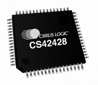
CS42428-CQZ Cirrus Logic Inc, CS42428-CQZ Datasheet - Page 3

CS42428-CQZ
Manufacturer Part Number
CS42428-CQZ
Description
IC CODEC 8CH PLL 192KHZ 64-LQFP
Manufacturer
Cirrus Logic Inc
Type
Audio Codecr
Datasheet
1.CS42428-CQZ.pdf
(73 pages)
Specifications of CS42428-CQZ
Data Interface
Serial
Resolution (bits)
24 b
Number Of Adcs / Dacs
2 / 8
Sigma Delta
Yes
Dynamic Range, Adcs / Dacs (db) Typ
114 / 114
Voltage - Supply, Analog
4.75 V ~ 5.25 V
Voltage - Supply, Digital
3.13 V ~ 5.25 V
Operating Temperature
-10°C ~ 70°C
Mounting Type
Surface Mount
Package / Case
64-LQFP
Audio Codec Type
Stereo
No. Of Adcs
2
No. Of Dacs
8
No. Of Input Channels
2
No. Of Output Channels
15
Adc / Dac Resolution
24bit
Sampling Rate
192kSPS
Ic Interface Type
I2C
Lead Free Status / RoHS Status
Lead free / RoHS Compliant
For Use With
598-1499 - BOARD EVAL FOR CS42428 CODEC
Lead Free Status / RoHS Status
Lead free / RoHS Compliant, Lead free / RoHS Compliant
Other names
598-1031
Available stocks
Company
Part Number
Manufacturer
Quantity
Price
Company:
Part Number:
CS42428-CQZ
Manufacturer:
Cirrus Logic Inc
Quantity:
135
Company:
Part Number:
CS42428-CQZ
Manufacturer:
Cirrus Logic Inc
Quantity:
10 000
Company:
Part Number:
CS42428-CQZR
Manufacturer:
Cirrus Logic Inc
Quantity:
10 000
DS605F1
LIST OF FIGURES
7. PARAMETER DEFINITIONS ................................................................................................................ 60
8. APPENDIX A: EXTERNAL FILTERS ................................................................................................... 61
9. APPENDIX B: PLL FILTER .................................................................................................................. 62
10. APPENDIX C: ADC FILTER PLOTS .................................................................................................. 64
11. APPENDIX D: DAC FILTER PLOTS .................................................................................................. 66
12. PACKAGE DIMENSIONS
13. ORDERING INFORMATION .............................................................................................................. 71
14. REFERENCES .................................................................................................................................... 71
15. REVISION HISTORY ......................................................................................................................... 72
Figure 1.Serial Audio Port Master Mode Timing ....................................................................................... 11
Figure 2.Serial Audio Port Slave Mode Timing ......................................................................................... 11
Figure 3.Control Port Timing - I²C Format ................................................................................................. 12
Figure 4.Control Port Timing - SPI Format ................................................................................................ 13
Figure 5.Typical Connection Diagram ....................................................................................................... 18
Figure 6.Typical Connection Diagram using the PLL ................................................................................ 19
Figure 7.Full-Scale Analog Input ............................................................................................................... 20
Figure 8.Full-Scale Output ........................................................................................................................ 21
Figure 9.ATAPI Block Diagram (x = channel pair 1, 2, 3, 4) ..................................................................... 22
Figure 10.Clock Generation ...................................................................................................................... 23
Figure 11.Right-Justified Serial Audio Formats ......................................................................................... 27
Figure 12.I²S Serial Audio Formats ........................................................................................................... 28
Figure 13.Left-Justified Serial Audio Formats ........................................................................................... 28
Figure 14.One Line Mode #1 Serial Audio Format .................................................................................... 29
Figure 15.One Line Mode #2 Serial Audio Format .................................................................................... 29
THERMAL CHARACTERISTICS .......................................................................................................... 70
6.7 Clock Control (address 06h) ........................................................................................................... 48
6.8 OMCK/PLL_CLK Ratio (address 07h) (Read Only) ....................................................................... 49
6.9 Clock Status (address 08h) (Read Only) ........................................................................................ 50
6.10 Volume Transition Control (address 0Dh) .................................................................................... 51
6.11 Channel Mute (address 0Eh) ........................................................................................................ 52
6.12 Volume Control (addresses 0Fh, 10h, 11h, 12h, 13h, 14h, 15h, 16h)
6.13 Channel Invert (address 17h) ....................................................................................................... 53
6.14 Mixing Control Pair 1 (Channels A1 & B1)(address 18h)
6.15 ADC Left Channel Gain (address 1Ch) ........................................................................................ 55
6.16 ADC Right Channel Gain (address 1Dh) ...................................................................................... 55
6.17 Interrupt Control (address 1Eh) .................................................................................................... 55
6.18 Interrupt Status (address 20h) (Read Only) ................................................................................. 56
6.19 Interrupt Mask (address 21h) ....................................................................................................... 57
6.20 Interrupt Mode MSB (address 22h)
6.21 Mutec Pin Control (address 28h) .................................................................................................. 57
6.22 General-Purpose Pin Control (addresses 29h to 2Fh) ................................................................. 58
8.1 ADC Input Filter .............................................................................................................................. 61
8.2 DAC Output Filter ........................................................................................................................... 61
9.1 External Filter Components ............................................................................................................ 62
9.1.1 General .................................................................................................................................. 62
9.1.2 Capacitor Selection ............................................................................................................... 62
9.1.3 Circuit Board Layout .............................................................................................................. 63
Mixing Control Pair 2 (Channels A2 & B2)(address 19h)
Mixing Control Pair 3 (Channels A3 & B3)(address 1Ah)
Mixing Control Pair 4 (Channels A4 & B4)(address 1Bh) ............................................................ 53
Interrupt Mode LSB (address 23h) ............................................................................................... 57
............................................................................................................... 70
...................................... 53
CS42428
3


