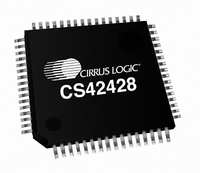
CS42428-CQZ Cirrus Logic Inc, CS42428-CQZ Datasheet - Page 4

CS42428-CQZ
Manufacturer Part Number
CS42428-CQZ
Description
IC CODEC 8CH PLL 192KHZ 64-LQFP
Manufacturer
Cirrus Logic Inc
Type
Audio Codecr
Datasheet
1.CS42428-CQZ.pdf
(73 pages)
Specifications of CS42428-CQZ
Data Interface
Serial
Resolution (bits)
24 b
Number Of Adcs / Dacs
2 / 8
Sigma Delta
Yes
Dynamic Range, Adcs / Dacs (db) Typ
114 / 114
Voltage - Supply, Analog
4.75 V ~ 5.25 V
Voltage - Supply, Digital
3.13 V ~ 5.25 V
Operating Temperature
-10°C ~ 70°C
Mounting Type
Surface Mount
Package / Case
64-LQFP
Audio Codec Type
Stereo
No. Of Adcs
2
No. Of Dacs
8
No. Of Input Channels
2
No. Of Output Channels
15
Adc / Dac Resolution
24bit
Sampling Rate
192kSPS
Ic Interface Type
I2C
Lead Free Status / RoHS Status
Lead free / RoHS Compliant
For Use With
598-1499 - BOARD EVAL FOR CS42428 CODEC
Lead Free Status / RoHS Status
Lead free / RoHS Compliant, Lead free / RoHS Compliant
Other names
598-1031
Available stocks
Company
Part Number
Manufacturer
Quantity
Price
Company:
Part Number:
CS42428-CQZ
Manufacturer:
Cirrus Logic Inc
Quantity:
135
Company:
Part Number:
CS42428-CQZ
Manufacturer:
Cirrus Logic Inc
Quantity:
10 000
Company:
Part Number:
CS42428-CQZR
Manufacturer:
Cirrus Logic Inc
Quantity:
10 000
CS42428
Figure 16.ADCIN1/ADCIN2 Serial Audio Format ...................................................................................... 30
Figure 17.OLM Configuration #1 ............................................................................................................... 31
Figure 18.OLM Configuration #2 ............................................................................................................... 32
Figure 19.OLM Configuration #3 ............................................................................................................... 33
Figure 20.OLM Configuration #4 ............................................................................................................... 34
Figure 21.Control Port Timing in SPI Mode .............................................................................................. 35
Figure 22.Control Port Timing, I²C Write ................................................................................................... 36
Figure 23.Control Port Timing, I²C Read ................................................................................................... 36
Figure 24.Recommended Analog Input Buffer .......................................................................................... 61
Figure 25.Recommended Analog Output Buffer ....................................................................................... 61
Figure 26.Recommended Layout Example ............................................................................................... 63
Figure 27.Single-Speed Mode Stopband Rejection .................................................................................. 64
Figure 28.Single-Speed Mode Transition Band ........................................................................................ 64
Figure 29.Single-Speed Mode Transition Band (Detail) ............................................................................ 64
Figure 30.Single-Speed Mode Passband Ripple ...................................................................................... 64
Figure 31.Double-Speed Mode Stopband Rejection ................................................................................. 64
Figure 32.Double-Speed Mode Transition Band ....................................................................................... 64
Figure 33.Double-Speed Mode Transition Band (Detail) .......................................................................... 65
Figure 34.Double-Speed Mode Passband Ripple ..................................................................................... 65
Figure 35.Quad-Speed Mode Stopband Rejection ................................................................................... 65
Figure 36.Quad-Speed Mode Transition Band ......................................................................................... 65
Figure 37.Quad-Speed Mode Transition Band (Detail) ............................................................................. 65
Figure 38.Quad-Speed Mode Passband Ripple ....................................................................................... 65
Figure 39.Single-Speed (fast) Stopband Rejection ................................................................................... 66
Figure 40.Single-Speed (fast) Transition Band ......................................................................................... 66
Figure 41.Single-Speed (fast) Transition Band (detail) ............................................................................. 66
Figure 42.Single-Speed (fast) Passband Ripple ....................................................................................... 66
Figure 43.Single-Speed (slow) Stopband Rejection ................................................................................. 66
Figure 44.Single-Speed (slow) Transition Band ........................................................................................ 66
Figure 45.Single-Speed (slow) Transition Band (detail) ............................................................................ 67
Figure 46.Single-Speed (slow) Passband Ripple ...................................................................................... 67
Figure 47.Double-Speed (fast) Stopband Rejection ................................................................................. 67
Figure 48.Double-Speed (fast) Transition Band ........................................................................................ 67
Figure 49.Double-Speed (fast) Transition Band (detail) ............................................................................ 67
Figure 50.Double-Speed (fast) Passband Ripple ...................................................................................... 67
Figure 51.Double-Speed (slow) Stopband Rejection ................................................................................ 68
Figure 52.Double-Speed (slow) Transition Band ...................................................................................... 68
Figure 53.Double-Speed (slow) Transition Band (detail) .......................................................................... 68
Figure 54.Double-Speed (slow) Passband Ripple .................................................................................... 68
Figure 55.Quad-Speed (fast) Stopband Rejection .................................................................................... 68
Figure 56.Quad-Speed (fast) Transition Band .......................................................................................... 68
Figure 57.Quad-Speed (fast) Transition Band (detail) .............................................................................. 69
Figure 58.Quad-Speed (fast) Passband Ripple ........................................................................................ 69
Figure 59.Quad-Speed (slow) Stopband Rejection ................................................................................... 69
Figure 60.Quad-Speed (slow) Transition Band ......................................................................................... 69
Figure 61.Quad-Speed (slow) Transition Band (detail) ............................................................................. 69
Figure 62.Quad-Speed (slow) Passband Ripple ....................................................................................... 69
4
DS605F1


