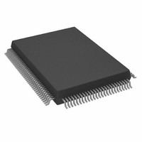
AD9888KSZ-140 Analog Devices Inc, AD9888KSZ-140 Datasheet - Page 18

AD9888KSZ-140
Manufacturer Part Number
AD9888KSZ-140
Description
IC FLAT PANEL INTERFACE 128-MQFP
Manufacturer
Analog Devices Inc
Datasheet
1.AD9888KSZ-205.pdf
(32 pages)
Specifications of AD9888KSZ-140
Applications
Graphic Cards, VGA Interfaces
Interface
2-Wire Serial
Voltage - Supply
3 V ~ 3.6 V
Package / Case
128-MQFP, 128-PQFP
Mounting Type
Surface Mount
Supply Current
200mA
Power Dissipation Pd
850mW
Supply Voltage Range
3V To 3.6V, 2.2V To 3.6V
Digital Ic Case Style
MQFP
No. Of Pins
128
Operating Temperature Range
0°C To +70°C
Svhc
No SVHC
Number Of Elements
3
Resolution
8Bit
Sample Rate
140MSPS
Input Polarity
Bipolar
Input Type
Voltage
Rated Input Volt
±0.25/±0.5V
Differential Input
No
Power Supply Requirement
Single
Single Supply Voltage (typ)
3.3V
Single Supply Voltage (min)
3V
Single Supply Voltage (max)
3.6V
Dual Supply Voltage (typ)
Not RequiredV
Dual Supply Voltage (min)
Not RequiredV
Dual Supply Voltage (max)
Not RequiredV
Power Dissipation
1.05W
Differential Linearity Error
±1.35LSB
Integral Nonlinearity Error
±2.5LSB
Operating Temp Range
0C to 70C
Operating Temperature Classification
Commercial
Mounting
Surface Mount
Pin Count
128
Package Type
MQFP
Input Signal Type
Single-Ended
Interface Type
2-wire, Serial
Rohs Compliant
Yes
Lead Free Status / RoHS Status
Lead free / RoHS Compliant
Lead Free Status / RoHS Status
Lead free / RoHS Compliant, Lead free / RoHS Compliant
Available stocks
Company
Part Number
Manufacturer
Quantity
Price
Company:
Part Number:
AD9888KSZ-140
Manufacturer:
AD
Quantity:
217
Company:
Part Number:
AD9888KSZ-140
Manufacturer:
ADI
Quantity:
482
Company:
Part Number:
AD9888KSZ-140
Manufacturer:
Analog Devices Inc
Quantity:
10 000
AD9888
Read and
Hex
Address Read Only
0EH
0FH
10H
11H
12H
13H
Write or
R/W
R/W
R/W
R/W
R/W
R/W
7:0
7:1
7:3
7:0
7:0
7:0
Bits
Default
Value
0******* Sync Control
*1******
**0*****
***0****
****0***
*****0**
******0*
*******0
0*******
*1******
**0*****
***0****
****1***
*****1**
******1*
01111*** Sync-on-Green
*****0**
******0*
*******0
00100000 Sync Separator
00000000 Pre-COAST
00000000 Post-COAST
Register Name
Threshold
Threshold
Table V. Control Register Map (continued)
Function
Bit 7—Hsync Polarity Override. (Logic 0 = Polarity determined by chip,
Logic 1 = Polarity set by Bit 6 in Register 0EH.)
Bit 6—Hsync Input Polarity. Indicates to the PLL the polarity of the in
coming Hsync signal. (Logic 0 = active low, Logic 1 = active high.)
Bit 5—Hsync Output Polarity. (Logic 0 = Logic High Sync, Logic 1 =
Logic Low Sync).
Bit 4—Active Hsync Override. If set to Logic 1, the user can select the
Hsync to be used via Bit 3. If set to Logic 0, the active interface is selected
via Bit 6 in Register 14H.
Bit 3—Active Hsync Select. Logic 0 selects Hsync as the active sync.
Logic 1 selects Sync-on-Green as the active sync. Note: the indicated
Hsync will be used only if Bit 4 is set to Logic 1 or if both syncs are active
(Bits 1, 7 = Logic 1 in register 14H).
Bit 2—Vsync Output Invert. (Logic 0 = Invert, Logic 1 = No Invert.)
Bit 1—Active Vsync Override. If set to Logic 1, the user can select the
Vsync to be used via Bit 0. If set to Logic 0, the active interface is selected
via Bit 3 in Register 14H.
Bit 0—Active Vsync Select. Logic 0 selects Raw Vsync as the output Vsync.
Logic 1 selects Sync Separated Vsync as the output Vsync. Note: The indi-
cated Vsync will be used only if Bit 1 is set to Logic 1.
Bit 7—Clamp Function. Chooses between Hsync for Clamp signal or
another external signal to be used for clamping. (Logic 0 = Hsync,
Logic 1 = Clamp.)
Bit 6—Clamp Polarity. Valid only with external Clamp signal. (Logic 0 =
active high, Logic 1 selects active low.)
Bit 5—COAST select. Logic 0 selects the coast input pin to be used for the
PLL coast. Logic 1 selects Vsync to be used for the PLL coast.
Bit 4—COAST Polarity Override. (Logic 0 = Polarity determined by chip,
Logic 1 = Polarity set by Bit 3 in Register 0FH.)
Bit 3—COAST Polarity. Changes polarity of external COAST signal.
(Logic = 0 = active low, Logic 1 = active high.)
Bit 2—Seek Mode Override. (Logic 1 = allow low-power mode, Logic 0 =
disallow low power mode.)
Bit 1—PWRDN. Full Chip Power-Down, active low. (Logic 0 = Full Chip
Power-Down, Logic 1 = normal.)
Sync-on-Green Threshold — Sets the voltage level of the Sync-on-Green
slicer’s comparator.
Bit 2—Red Clamp Select – Logic 0 selects clamp to ground. Logic 1 selects
clamp to midscale (voltage at Pin 9).
Bit 1—Blue Clamp Select – Logic 0 selects clamp to ground. Logic 1 selects
clamp to midscale (voltage at Pin 24).
Bit 0—Must be set to 1 for proper operation.
Sync Separator Threshold – Sets how many internal 5 MHz clock periods
the sync separator will count to before toggling high or low. This should be
set to some number greater than the maximum Hsync or equalization
pulsewidth.
Pre-COAST – Sets the number of Hsync periods that coast becomes active
prior to Vsync.
Post-COAST – Sets the number of Hsync periods that coast stays active
following Vsync.
–18–
REV. B


