TMPSNS-RTD1 Microchip Technology, TMPSNS-RTD1 Datasheet - Page 305
TMPSNS-RTD1
Manufacturer Part Number
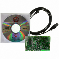
TMPSNS-RTD1
Description
BOARD EVAL PT100 RTD TEMP SENSOR
Manufacturer
Microchip Technology
Datasheets
1.MCP3301-CIMS.pdf
(32 pages)
2.PCM18XR1.pdf
(438 pages)
3.MCP6S22DM-PICTL.pdf
(43 pages)
4.TMPSNS-RTD1.pdf
(26 pages)
Specifications of TMPSNS-RTD1
Sensor Type
Temperature
Interface
USB
Embedded
Yes, MCU, 8-Bit
Utilized Ic / Part
MCP3301, MCP6S26, PIC18F2550
Processor To Be Evaluated
MCP6S26, MCP3301, MCP6024, MCP41010, PIC18F2550, TC1071, MCP6002
Data Bus Width
12 bit
Interface Type
USB
Lead Free Status / RoHS Status
Not applicable / Not applicable
Voltage - Supply
-
Sensitivity
-
Sensing Range
-
Lead Free Status / RoHS Status
Lead free / RoHS Compliant, Not applicable / Not applicable


25.2
For PIC18F2455/2550/4455/4550 devices, the WDT is
driven by the INTRC source. When the WDT is
enabled, the clock source is also enabled. The nominal
WDT period is 4 ms and has the same stability as the
INTRC oscillator.
The 4 ms period of the WDT is multiplied by a 16-bit
postscaler. Any output of the WDT postscaler is
selected by a multiplexer, controlled by bits in Configu-
ration Register 2H. Available periods range from 4 ms
to 131.072 seconds (2.18 minutes). The WDT and
postscaler are cleared when any of the following events
occur: a SLEEP or CLRWDT instruction is executed, the
IRCF bits (OSCCON<6:4>) are changed or a clock
failure has occurred.
.
FIGURE 25-1:
© 2009 Microchip Technology Inc.
Change on IRCF bits
All Device Resets
Watchdog Timer (WDT)
INTRC Source
WDTPS<3:0>
SWDTEN
WDTEN
CLRWDT
SLEEP
WDT BLOCK DIAGRAM
Enable WDT
WDT Counter
÷128
PIC18F2455/2550/4455/4550
4
INTRC Control
Programmable Postscaler
1:1 to 1:32,768
25.2.1
Register 25-15 shows the WDTCON register. This is a
readable and writable register which contains a control
bit that allows software to override the WDT enable
Configuration bit, but only if the Configuration bit has
disabled the WDT.
Note 1: The CLRWDT and SLEEP instructions
2: Changing the setting of the IRCF bits
3: When a CLRWDT instruction is executed,
WDT
CONTROL REGISTER
clear the WDT and postscaler counts
when executed.
(OSCCON<6:4>) clears the WDT and
postscaler counts.
the postscaler count will be cleared.
Reset
Wake-up from
Power-Managed
Modes
WDT
Reset
DS39632E-page 303
Related parts for TMPSNS-RTD1
Image
Part Number
Description
Manufacturer
Datasheet
Request
R

Part Number:
Description:
Manufacturer:
Microchip Technology Inc.
Datasheet:
Part Number:
Description:
Manufacturer:
Microchip Technology Inc.
Datasheet:
Part Number:
Description:
Manufacturer:
Microchip Technology Inc.
Datasheet:
Part Number:
Description:
Manufacturer:
Microchip Technology Inc.
Datasheet:
Part Number:
Description:
Manufacturer:
Microchip Technology Inc.
Datasheet:
Part Number:
Description:
Manufacturer:
Microchip Technology Inc.
Datasheet:
Part Number:
Description:
Manufacturer:
Microchip Technology Inc.
Datasheet:
Part Number:
Description:
Manufacturer:
Microchip Technology Inc.
Datasheet: