TMPSNS-RTD1 Microchip Technology, TMPSNS-RTD1 Datasheet - Page 9
TMPSNS-RTD1
Manufacturer Part Number
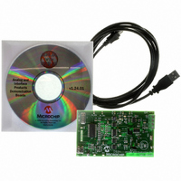
TMPSNS-RTD1
Description
BOARD EVAL PT100 RTD TEMP SENSOR
Manufacturer
Microchip Technology
Datasheets
1.MCP3301-CIMS.pdf
(32 pages)
2.PCM18XR1.pdf
(438 pages)
3.MCP6S22DM-PICTL.pdf
(43 pages)
4.TMPSNS-RTD1.pdf
(26 pages)
Specifications of TMPSNS-RTD1
Sensor Type
Temperature
Interface
USB
Embedded
Yes, MCU, 8-Bit
Utilized Ic / Part
MCP3301, MCP6S26, PIC18F2550
Processor To Be Evaluated
MCP6S26, MCP3301, MCP6024, MCP41010, PIC18F2550, TC1071, MCP6002
Data Bus Width
12 bit
Interface Type
USB
Lead Free Status / RoHS Status
Not applicable / Not applicable
Voltage - Supply
-
Sensitivity
-
Sensing Range
-
Lead Free Status / RoHS Status
Lead free / RoHS Compliant, Not applicable / Not applicable


1.0
This document contains device-specific information for
the following devices:
This family of devices offers the advantages of all
PIC18 microcontrollers – namely, high computational
performance at an economical price – with the addition
of
memory.
PIC18F2455/2550/4455/4550 family introduces design
enhancements that make these microcontrollers a log-
ical choice for many high-performance, power sensitive
applications.
1.1
1.1.1
All of the devices in the PIC18F2455/2550/4455/4550
family incorporate a range of features that can signifi-
cantly reduce power consumption during operation.
Key items include:
• Alternate Run Modes: By clocking the controller
• Multiple Idle Modes: The controller can also run
• On-the-Fly Mode Switching: The
• Low Consumption in Key Modules: The power
1.1.2
Devices in the PIC18F2455/2550/4455/4550 family
incorporate a fully featured Universal Serial Bus
communications module that is compliant with the USB
Specification Revision 2.0. The module supports both
low-speed and full-speed communication for all sup-
ported data transfer types. It also incorporates its own
on-chip transceiver and 3.3V regulator and supports
the use of external transceivers and voltage regulators.
© 2009 Microchip Technology Inc.
• PIC18F2455
• PIC18F2550
• PIC18F4455
• PIC18F4550
from the Timer1 source or the internal oscillator
block, power consumption during code execution
can be reduced by as much as 90%.
with its CPU core disabled but the peripherals still
active. In these states, power consumption can be
reduced even further, to as little as 4%, of normal
operation requirements.
power-managed modes are invoked by user code
during operation, allowing the user to incorporate
power-saving ideas into their application’s
software design.
requirements for both Timer1 and the Watchdog
Timer are minimized. See Section 28.0
“Electrical Characteristics” for values.
high-endurance,
DEVICE OVERVIEW
New Core Features
In
nanoWatt TECHNOLOGY
UNIVERSAL SERIAL BUS (USB)
addition
Enhanced
to
• PIC18LF2455
• PIC18LF2550
• PIC18LF4455
• PIC18LF4550
these
Flash
features,
PIC18F2455/2550/4455/4550
program
the
1.1.3
All of the devices in the PIC18F2455/2550/4455/4550
family offer twelve different oscillator options, allowing
users a wide range of choices in developing application
hardware. These include:
• Four Crystal modes using crystals or ceramic
• Four External Clock modes, offering the option of
• An internal oscillator block which provides an
• A Phase Lock Loop (PLL) frequency multiplier,
• Asynchronous dual clock operation, allowing the
Besides its availability as a clock source, the internal
oscillator block provides a stable reference source that
gives the family additional features for robust
operation:
• Fail-Safe Clock Monitor: This option constantly
• Two-Speed Start-up: This option allows the
resonators.
using two pins (oscillator input and a divide-by-4
clock output) or one pin (oscillator input, with the
second pin reassigned as general I/O).
8 MHz clock (±2% accuracy) and an INTRC
source (approximately 31 kHz, stable over
temperature and V
6 user-selectable clock frequencies, between
125 kHz to 4 MHz, for a total of 8 clock
use as an additional general purpose I/O.
available to both the High-Speed Crystal and
External Oscillator modes, which allows a wide
range of clock speeds from 4 MHz to 48 MHz.
USB module to run from a high-frequency
oscillator while the rest of the microcontroller is
clocked from an internal low-power oscillator.
monitors the main clock source against a
reference signal provided by the internal
oscillator. If a clock failure occurs, the controller is
switched to the internal oscillator block, allowing
for continued low-speed operation or a safe
application shutdown.
internal oscillator to serve as the clock source
from Power-on Reset, or wake-up from Sleep
mode, until the primary clock source is available.
frequencies. This option frees an oscillator pin for
MULTIPLE OSCILLATOR OPTIONS
AND FEATURES
DD
), as well as a range of
DS39632E-page 7
Related parts for TMPSNS-RTD1
Image
Part Number
Description
Manufacturer
Datasheet
Request
R

Part Number:
Description:
Manufacturer:
Microchip Technology Inc.
Datasheet:
Part Number:
Description:
Manufacturer:
Microchip Technology Inc.
Datasheet:
Part Number:
Description:
Manufacturer:
Microchip Technology Inc.
Datasheet:
Part Number:
Description:
Manufacturer:
Microchip Technology Inc.
Datasheet:
Part Number:
Description:
Manufacturer:
Microchip Technology Inc.
Datasheet:
Part Number:
Description:
Manufacturer:
Microchip Technology Inc.
Datasheet:
Part Number:
Description:
Manufacturer:
Microchip Technology Inc.
Datasheet:
Part Number:
Description:
Manufacturer:
Microchip Technology Inc.
Datasheet: