TMPSNS-RTD1 Microchip Technology, TMPSNS-RTD1 Datasheet - Page 39
TMPSNS-RTD1
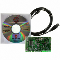
Manufacturer Part Number
TMPSNS-RTD1
Description
BOARD EVAL PT100 RTD TEMP SENSOR
Manufacturer
Microchip Technology
Datasheets
1.MCP3301-CIMS.pdf
(32 pages)
2.PCM18XR1.pdf
(438 pages)
3.MCP6S22DM-PICTL.pdf
(43 pages)
4.TMPSNS-RTD1.pdf
(26 pages)
Specifications of TMPSNS-RTD1
Sensor Type
Temperature
Interface
USB
Embedded
Yes, MCU, 8-Bit
Utilized Ic / Part
MCP3301, MCP6S26, PIC18F2550
Processor To Be Evaluated
MCP6S26, MCP3301, MCP6024, MCP41010, PIC18F2550, TC1071, MCP6002
Data Bus Width
12 bit
Interface Type
USB
Lead Free Status / RoHS Status
Not applicable / Not applicable
Voltage - Supply
-
Sensitivity
-
Sensing Range
-
Lead Free Status / RoHS Status
Lead free / RoHS Compliant, Not applicable / Not applicable


SEC_RUN mode is entered by setting the SCS1:SCS0
bits to ‘01’. The device clock source is switched to the
Timer1 oscillator (see Figure 3-1), the primary
oscillator is shut down, the T1RUN bit (T1CON<6>) is
set and the OSTS bit is cleared.
FIGURE 3-1:
FIGURE 3-2:
© 2009 Microchip Technology Inc.
Note:
Note 1:
Peripheral
Program
Counter
T1OSI
OSC1
Clock
Clock
Note 1:
CPU
CPU Clock
The Timer1 oscillator should already be
running prior to entering SEC_RUN mode.
If the T1OSCEN bit is not set when the
SCS1:SCS0 bits are set to ‘01’, entry to
SEC_RUN mode will not occur. If the
Timer1 oscillator is enabled but not yet
running, device clocks will be delayed until
the
situations, initial oscillator operation is far
from stable and unpredictable operation
may result.
PLL Clock
Peripheral
Program
Counter
Output
T1OSI
OSC1
Clock
Clock transition typically occurs within 2-4 T
2:
oscillator
SCS1:SCS0 bits Changed
Q1
T
Clock transition typically occurs within 2-4 T
OST
TRANSITION TIMING FOR ENTRY TO SEC_RUN MODE
TRANSITION TIMING FROM SEC_RUN MODE TO PRI_RUN MODE (HSPLL)
Q2
= 1024 T
PC
Q3
has started.
Q4
OSC
Q1
Q1
; T
T
PLL
OST
1
= 2 ms (approx). These intervals are not shown to scale.
(1)
PC
Q2
2
In
PIC18F2455/2550/4455/4550
Clock Transition
T
such
3
PLL
OSTS bit Set
Q3
OSC
(1)
.
OSC
Q4
.
PC + 2
(1)
n-1
On transitions from SEC_RUN mode to PRI_RUN, the
peripherals and CPU continue to be clocked from the
Timer1 oscillator while the primary clock is started.
When the primary clock becomes ready, a clock switch
back to the primary clock occurs (see Figure 3-2).
When the clock switch is complete, the T1RUN bit is
cleared, the OSTS bit is set and the primary clock is
providing the clock. The IDLEN and SCS bits are not
affected by the wake-up; the Timer1 oscillator
continues to run.
Q1
1
n
Transition
2
Clock
(2)
n-1 n
PC + 2
Q2
Q3
Q2
Q4
Q3 Q4
Q1
Q1
PC + 4
Q2
Q2
PC + 4
DS39632E-page 37
Q3
Q3
Related parts for TMPSNS-RTD1
Image
Part Number
Description
Manufacturer
Datasheet
Request
R

Part Number:
Description:
Manufacturer:
Microchip Technology Inc.
Datasheet:
Part Number:
Description:
Manufacturer:
Microchip Technology Inc.
Datasheet:
Part Number:
Description:
Manufacturer:
Microchip Technology Inc.
Datasheet:
Part Number:
Description:
Manufacturer:
Microchip Technology Inc.
Datasheet:
Part Number:
Description:
Manufacturer:
Microchip Technology Inc.
Datasheet:
Part Number:
Description:
Manufacturer:
Microchip Technology Inc.
Datasheet:
Part Number:
Description:
Manufacturer:
Microchip Technology Inc.
Datasheet:
Part Number:
Description:
Manufacturer:
Microchip Technology Inc.
Datasheet: