TMPSNS-RTD1 Microchip Technology, TMPSNS-RTD1 Datasheet - Page 51
TMPSNS-RTD1
Manufacturer Part Number
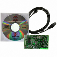
TMPSNS-RTD1
Description
BOARD EVAL PT100 RTD TEMP SENSOR
Manufacturer
Microchip Technology
Datasheets
1.MCP3301-CIMS.pdf
(32 pages)
2.PCM18XR1.pdf
(438 pages)
3.MCP6S22DM-PICTL.pdf
(43 pages)
4.TMPSNS-RTD1.pdf
(26 pages)
Specifications of TMPSNS-RTD1
Sensor Type
Temperature
Interface
USB
Embedded
Yes, MCU, 8-Bit
Utilized Ic / Part
MCP3301, MCP6S26, PIC18F2550
Processor To Be Evaluated
MCP6S26, MCP3301, MCP6024, MCP41010, PIC18F2550, TC1071, MCP6002
Data Bus Width
12 bit
Interface Type
USB
Lead Free Status / RoHS Status
Not applicable / Not applicable
Voltage - Supply
-
Sensitivity
-
Sensing Range
-
Lead Free Status / RoHS Status
Lead free / RoHS Compliant, Not applicable / Not applicable


4.5
PIC18F2455/2550/4455/4550
three separate on-chip timers that help regulate the
Power-on Reset process. Their main function is to
ensure that the device clock is stable before code is
executed. These timers are:
• Power-up Timer (PWRT)
• Oscillator Start-up Timer (OST)
• PLL Lock Time-out
4.5.1
The Power-up Timer (PWRT) of the PIC18F2455/2550/
4455/4550 devices is an 11-bit counter which uses the
INTRC source as the clock input. This yields an
approximate time interval of 2048 x 32 μs = 65.6 ms.
While the PWRT is counting, the device is held in
Reset.
The power-up time delay depends on the INTRC clock
and will vary from chip to chip due to temperature and
process variation. See DC parameter 33 (Table 28-12)
for details.
The PWRT is enabled by clearing the PWRTEN
Configuration bit.
4.5.2
The Oscillator Start-up Timer (OST) provides a
1024 oscillator cycle (from OSC1 input) delay after the
PWRT delay is over (parameter 33, Table 28-12). This
ensures that the crystal oscillator or resonator has
started and stabilized.
The OST time-out is invoked only for XT, HS and
HSPLL modes and only on Power-on Reset or on exit
from most power-managed modes.
TABLE 4-2:
© 2009 Microchip Technology Inc.
HS, XT
HSPLL, XTPLL
EC, ECIO
ECPLL, ECPIO
INTIO, INTCKO
INTHS, INTXT
Note 1:
Configuration
2:
Oscillator
Device Reset Timers
66 ms (65.5 ms) is the nominal Power-up Timer (PWRT) delay.
2 ms is the nominal time required for the PLL to lock.
POWER-UP TIMER (PWRT)
OSCILLATOR START-UP
TIMER (OST)
TIME-OUT IN VARIOUS SITUATIONS
66 ms
66 ms
66 ms
(1)
devices
66 ms
PWRTEN = 0
+ 1024 T
(1)
(1)
66 ms
66 ms
(1)
+ 1024 T
+ 1024 T
+ 2 ms
incorporate
Power-up
OSC
(1)
(1)
PIC18F2455/2550/4455/4550
+ 2 ms
OSC
(2)
OSC
(2)
(2)
and Brown-out
4.5.3
With the PLL enabled in its PLL mode, the time-out
sequence following a Power-on Reset is slightly differ-
ent from other oscillator modes. A separate timer is
used to provide a fixed time-out that is sufficient for the
PLL to lock to the main oscillator frequency. This PLL
lock time-out (T
oscillator start-up time-out.
4.5.4
On power-up, the time-out sequence is as follows:
1.
2.
The total time-out will vary based on oscillator configu-
ration and the status of the PWRT. Figure 4-3,
Figure 4-4, Figure 4-5, Figure 4-6 and Figure 4-7 all
depict time-out sequences on power-up, with the
Power-up Timer enabled and the device operating in
HS Oscillator mode. Figures 4-3 through 4-6 also apply
to devices operating in XT mode. For devices in RC
mode and with the PWRT disabled, on the other hand,
there will be no time-out at all.
Since the time-outs occur from the POR pulse, if MCLR
is kept low long enough, all time-outs will expire. Bring-
ing MCLR high will begin execution immediately
(Figure 4-5). This is useful for testing purposes or to
synchronize more than one PIC18FXXXX device
operating in parallel.
1024 T
PWRTEN = 1
After the POR condition has cleared, PWRT
time-out is invoked (if enabled).
Then, the OST is activated.
1024 T
1024 T
2 ms
OSC
—
—
PLL LOCK TIME-OUT
TIME-OUT SEQUENCE
+ 2 ms
OSC
(2)
OSC
PLL
(2)
) is typically 2 ms and follows the
Power-Managed Mode
1024 T
1024 T
1024 T
Exit from
DS39632E-page 49
2 ms
OSC
—
—
+ 2 ms
OSC
(2)
OSC
(2)
Related parts for TMPSNS-RTD1
Image
Part Number
Description
Manufacturer
Datasheet
Request
R

Part Number:
Description:
Manufacturer:
Microchip Technology Inc.
Datasheet:
Part Number:
Description:
Manufacturer:
Microchip Technology Inc.
Datasheet:
Part Number:
Description:
Manufacturer:
Microchip Technology Inc.
Datasheet:
Part Number:
Description:
Manufacturer:
Microchip Technology Inc.
Datasheet:
Part Number:
Description:
Manufacturer:
Microchip Technology Inc.
Datasheet:
Part Number:
Description:
Manufacturer:
Microchip Technology Inc.
Datasheet:
Part Number:
Description:
Manufacturer:
Microchip Technology Inc.
Datasheet:
Part Number:
Description:
Manufacturer:
Microchip Technology Inc.
Datasheet: