TMPSNS-RTD1 Microchip Technology, TMPSNS-RTD1 Datasheet - Page 38
TMPSNS-RTD1
Manufacturer Part Number
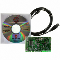
TMPSNS-RTD1
Description
BOARD EVAL PT100 RTD TEMP SENSOR
Manufacturer
Microchip Technology
Datasheets
1.MCP3301-CIMS.pdf
(32 pages)
2.PCM18XR1.pdf
(438 pages)
3.MCP6S22DM-PICTL.pdf
(43 pages)
4.TMPSNS-RTD1.pdf
(26 pages)
Specifications of TMPSNS-RTD1
Sensor Type
Temperature
Interface
USB
Embedded
Yes, MCU, 8-Bit
Utilized Ic / Part
MCP3301, MCP6S26, PIC18F2550
Processor To Be Evaluated
MCP6S26, MCP3301, MCP6024, MCP41010, PIC18F2550, TC1071, MCP6002
Data Bus Width
12 bit
Interface Type
USB
Lead Free Status / RoHS Status
Not applicable / Not applicable
Voltage - Supply
-
Sensitivity
-
Sensing Range
-
Lead Free Status / RoHS Status
Lead free / RoHS Compliant, Not applicable / Not applicable


PIC18F2455/2550/4455/4550
3.1.3
The length of the transition between clock sources is
the sum of two cycles of the old clock source and three
to four cycles of the new clock source. This formula
assumes that the new clock source is stable.
Three bits indicate the current clock source and its
status. They are:
• OSTS (OSCCON<3>)
• IOFS (OSCCON<2>)
• T1RUN (T1CON<6>)
In general, only one of these bits will be set while in a
given power-managed mode. When the OSTS bit is
set, the primary clock is providing the device clock.
When the IOFS bit is set, the INTOSC output is provid-
ing a stable, 8 MHz clock source to a divider that
actually drives the device clock. When the T1RUN bit is
set, the Timer1 oscillator is providing the clock. If none
of these bits are set, then either the INTRC clock
source is clocking the device, or the INTOSC source is
not yet stable.
If the internal oscillator block is configured as the
primary clock source by the FOSC3:FOSC0 Con-
figuration bits, then both the OSTS and IOFS bits may
be set when in PRI_RUN or PRI_IDLE modes. This
indicates that the primary clock (INTOSC output) is
EXAMPLE 3-1:
3.2
In the Run modes, clocks to both the core and
peripherals are active. The difference between these
modes is the clock source.
3.2.1
The PRI_RUN mode is the normal, full-power execu-
tion mode of the microcontroller. This is also the default
mode upon a device Reset unless Two-Speed Start-up
is enabled (see Section 25.3 “Two-Speed Start-up”
for details). In this mode, the OSTS bit is set. The IOFS
bit may be set if the internal oscillator block is the
primary clock source (see Section 2.4.1 “Oscillator
Control Register”).
DS39632E-page 36
SLEEP
NOP
SLEEP
Run Modes
;Wait at least 1 Tcy before executing another sleep instruction
CLOCK TRANSITIONS AND
STATUS INDICATORS
PRI_RUN MODE
EXECUTING BACK TO BACK SLEEP INSTRUCTIONS
generating a stable 8 MHz output. Entering another
power-managed RC mode at the same frequency
would clear the OSTS bit.
3.1.4
The power-managed mode that is invoked with the
SLEEP instruction is determined by the setting of the
IDLEN bit at the time the instruction is executed. If
another SLEEP instruction is executed, the device will
enter the power-managed mode specified by IDLEN at
that time. If IDLEN has changed, the device will enter
the new power-managed mode specified by the new
setting.
Upon resuming normal operation after waking from
Sleep or Idle, the internal state machines require at
least one T
can be executed. If two back to back SLEEP instruc-
tions will be executed, the process shown in
Example 3-1 should be used.
3.2.2
The SEC_RUN mode is the compatible mode to the
“clock switching” feature offered in other PIC18
devices. In this mode, the CPU and peripherals are
clocked from the Timer1 oscillator. This gives users the
option of lower power consumption while still using a
high-accuracy clock source.
Note 1: Caution should be used when modifying a
2: Executing a SLEEP instruction does not
CY
MULTIPLE SLEEP COMMANDS
SEC_RUN MODE
single IRCF bit. If V
possible to select a higher clock speed
than is supported by the low V
Improper device operation may result if
the V
necessarily place the device into Sleep
mode. It acts as the trigger to place the
controller into either the Sleep mode, or
one of the Idle modes, depending on the
setting of the IDLEN bit.
delay before another SLEEP instruction
DD
/F
OSC
© 2009 Microchip Technology Inc.
specifications are violated.
DD
is less than 3V, it is
DD
.
Related parts for TMPSNS-RTD1
Image
Part Number
Description
Manufacturer
Datasheet
Request
R

Part Number:
Description:
Manufacturer:
Microchip Technology Inc.
Datasheet:
Part Number:
Description:
Manufacturer:
Microchip Technology Inc.
Datasheet:
Part Number:
Description:
Manufacturer:
Microchip Technology Inc.
Datasheet:
Part Number:
Description:
Manufacturer:
Microchip Technology Inc.
Datasheet:
Part Number:
Description:
Manufacturer:
Microchip Technology Inc.
Datasheet:
Part Number:
Description:
Manufacturer:
Microchip Technology Inc.
Datasheet:
Part Number:
Description:
Manufacturer:
Microchip Technology Inc.
Datasheet:
Part Number:
Description:
Manufacturer:
Microchip Technology Inc.
Datasheet: