TMPSNS-RTD1 Microchip Technology, TMPSNS-RTD1 Datasheet - Page 32
TMPSNS-RTD1
Manufacturer Part Number
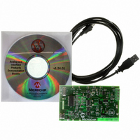
TMPSNS-RTD1
Description
BOARD EVAL PT100 RTD TEMP SENSOR
Manufacturer
Microchip Technology
Datasheets
1.MCP3301-CIMS.pdf
(32 pages)
2.PCM18XR1.pdf
(438 pages)
3.MCP6S22DM-PICTL.pdf
(43 pages)
4.TMPSNS-RTD1.pdf
(26 pages)
Specifications of TMPSNS-RTD1
Sensor Type
Temperature
Interface
USB
Embedded
Yes, MCU, 8-Bit
Utilized Ic / Part
MCP3301, MCP6S26, PIC18F2550
Processor To Be Evaluated
MCP6S26, MCP3301, MCP6024, MCP41010, PIC18F2550, TC1071, MCP6002
Data Bus Width
12 bit
Interface Type
USB
Lead Free Status / RoHS Status
Not applicable / Not applicable
Voltage - Supply
-
Sensitivity
-
Sensing Range
-
Lead Free Status / RoHS Status
Lead free / RoHS Compliant, Not applicable / Not applicable


PIC18F2455/2550/4455/4550
2.3
When these devices are used for USB connectivity,
they must have either a 6 MHz or 48 MHz clock for
USB operation, depending on whether Low-Speed or
Full-Speed mode is being used. This may require some
forethought in selecting an oscillator frequency and
programming the device.
The full range of possible oscillator configurations
compatible with USB operation is shown in Table 2-3.
2.3.1
The USB clock for Low-Speed mode is derived from the
primary oscillator chain and not directly from the PLL. It
is divided by 4 to produce the actual 6 MHz clock.
Because of this, the microcontroller can only use a
clock frequency of 24 MHz when the USB module is
TABLE 2-3:
DS39632E-page 30
Legend:
Note 1:
Input Oscillator
Frequency
48 MHz
48 MHz
40 MHz
24 MHz
Oscillator Settings for USB
All clock frequencies, except 24 MHz, are exclusively associated with full-speed USB operation (USB clock of 48 MHz).
Bold is used to highlight clock selections that are compatible with low-speed USB operation (system clock of 24 MHz,
USB clock of 6 MHz).
Only valid when the USBDIV Configuration bit is cleared.
LOW-SPEED OPERATION
OSCILLATOR CONFIGURATION OPTIONS FOR USB OPERATION
(PLLDIV2:PLLDIV0)
PLL Division
÷12 (111)
÷10 (110)
÷6 (101)
N/A
(1)
HSPLL, ECPLL, ECPIO
(FOSC3:FOSC0)
ECPLL, ECPIO
ECPLL, ECPIO
HS, EC, ECIO
Clock Mode
EC, ECIO
EC, ECIO
EC, ECIO
active and the controller clock source is one of the
primary oscillator modes (XT, HS or EC, with or without
the PLL).
This restriction does not apply if the microcontroller
clock source is the secondary oscillator or internal
oscillator block.
2.3.2
The USB module, in either mode, can run asynchro-
nously with respect to the microcontroller core and
other peripherals. This means that applications can use
the primary oscillator for the USB clock while the micro-
controller runs from a separate clock source at a lower
speed. If it is necessary to run the entire application
from only one clock source, full-speed operation
provides a greater selection of microcontroller clock
frequencies.
(CPUDIV1:CPUDIV0)
MCU Clock Division
RUNNING DIFFERENT USB AND
MICROCONTROLLER CLOCKS
None (00)
None (00)
None (00)
None (00)
÷2 (01)
÷3 (10)
÷4 (11)
÷2 (01)
÷3 (10)
÷4 (11)
÷2 (00)
÷3 (01)
÷4 (10)
÷6 (11)
÷2 (01)
÷3 (10)
÷4 (11)
÷2 (00)
÷3 (01)
÷4 (10)
÷6 (11)
÷2 (01)
÷3 (10)
÷4 (11)
÷2 (00)
÷3 (01)
÷4 (10)
÷6 (11)
© 2009 Microchip Technology Inc.
Clock Frequency
Microcontroller
13.33 MHz
48 MHz
24 MHz
16 MHz
12 MHz
48 MHz
32 MHz
24 MHz
16 MHz
40 MHz
20 MHz
10 MHz
48 MHz
32 MHz
24 MHz
16 MHz
24 MHz
48 MHz
24 MHz
16 MHz
12 MHz
12 MHz
48 MHz
32 MHz
24 MHz
16 MHz
8 MHz
6 MHz
Related parts for TMPSNS-RTD1
Image
Part Number
Description
Manufacturer
Datasheet
Request
R

Part Number:
Description:
Manufacturer:
Microchip Technology Inc.
Datasheet:
Part Number:
Description:
Manufacturer:
Microchip Technology Inc.
Datasheet:
Part Number:
Description:
Manufacturer:
Microchip Technology Inc.
Datasheet:
Part Number:
Description:
Manufacturer:
Microchip Technology Inc.
Datasheet:
Part Number:
Description:
Manufacturer:
Microchip Technology Inc.
Datasheet:
Part Number:
Description:
Manufacturer:
Microchip Technology Inc.
Datasheet:
Part Number:
Description:
Manufacturer:
Microchip Technology Inc.
Datasheet:
Part Number:
Description:
Manufacturer:
Microchip Technology Inc.
Datasheet: