C8051F330DK Silicon Laboratories Inc, C8051F330DK Datasheet - Page 197
C8051F330DK
Manufacturer Part Number
C8051F330DK
Description
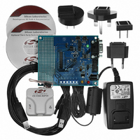
DEV KIT FOR C8051F330/F331
Manufacturer
Silicon Laboratories Inc
Type
MCUr
Specifications of C8051F330DK
Contents
Evaluation Board, Power Supply, USB Cables, Adapter and Documentation
Processor To Be Evaluated
C8051F33x
Interface Type
RS-232
Operating Supply Voltage
7 V to 15 V
Silicon Manufacturer
Silicon Labs
Core Architecture
8051
Silicon Core Number
C8051F330
Silicon Family Name
C8051F33x
Lead Free Status / RoHS Status
Contains lead / RoHS non-compliant
For Use With/related Products
Silicon Laboratories C8051F330, C8051F331
Lead Free Status / Rohs Status
Lead free / RoHS Compliant
Other names
336-1264


19.2.6. 16-Bit Pulse Width Modulator Mode
A PCA module may also be operated in 16-Bit PWM mode. In this mode, the 16-bit capture/compare mod-
ule defines the number of PCA clocks for the low time of the PWM signal. When the PCA counter matches
the module contents, the output on CEXn is asserted high; when the counter overflows, CEXn is asserted
low. To output a varying duty cycle, new value writes should be synchronized with PCA CCFn match inter-
rupts. 16-Bit PWM Mode is enabled by setting the ECOMn, PWMn, and PWM16n bits in the PCA0CPMn
register. For a varying duty cycle, match interrupts should be enabled (ECCFn = 1 AND MATn = 1) to help
synchronize the capture/compare register writes. The duty cycle for 16-Bit PWM Mode is given by
Equation 19.5.
Important Note About Capture/Compare Registers : When writing a 16-bit value to the PCA0 Cap-
ture/Compare registers, the low byte should always be written first. Writing to PCA0CPLn clears the
ECOMn bit to ‘0’; writing to PCA0CPHn sets ECOMn to ‘1’.
Using Equation 19.5, the largest duty cycle is 100% (PCA0CPn = 0), and the smallest duty cycle is
0.0015% (PCA0CPn = 0xFFFF). A 0% duty cycle may be generated by clearing the ECOMn bit to ‘0’.
19.3. Watchdog Timer Mode
A programmable watchdog timer (WDT) function is available through the PCA Module 2. The WDT is used
to generate a reset if the time between writes to the WDT update register (PCA0CPH2) exceed a specified
limit. The WDT can be configured and enabled/disabled as needed by software.
With the WDTE bit set in the PCA0MD register, Module 2 operates as a watchdog timer (WDT). The Mod-
ule 2 high byte is compared to the PCA counter high byte; the Module 2 low byte holds the offset to be
used when WDT updates are performed. The Watchdog Timer is enabled on reset. Writes to some
PCA registers are restricted while the Watchdog Timer is enabled.
PCA0CPLn
Write to
Reset
PCA0CPHn
Write to
0
ENB
ENB
1
W
P
M
1
6
n
1
E
C
O
M
n
PCA0CPMn
C
A
P
P
n
0 0 x 0
C
A
P
N
n
M
A
T
n
PCA Timebase
O
G
T
n
Equation 19.5. 16-Bit PWM Duty Cycle
W
P
M
n
E
C
C
F
n
x
Figure 19.9. PCA 16-Bit PWM Mode
DutyCycle
Enable
PCA0CPHn
PCA0H
=
16-bit Comparator
Rev. 1.7
---------------------------------------------------- -
65536 PCA0CPn
PCA0CPLn
PCA0L
–
65536
Overflow
C8051F330/1/2/3/4/5
match
S
R
SET
CLR
Q
Q
CEXn
Crossbar
Port I/O
201
Related parts for C8051F330DK
Image
Part Number
Description
Manufacturer
Datasheet
Request
R

Part Number:
Description:
SMD/C°/SINGLE-ENDED OUTPUT SILICON OSCILLATOR
Manufacturer:
Silicon Laboratories Inc
Part Number:
Description:
Manufacturer:
Silicon Laboratories Inc
Datasheet:
Part Number:
Description:
N/A N/A/SI4010 AES KEYFOB DEMO WITH LCD RX
Manufacturer:
Silicon Laboratories Inc
Datasheet:
Part Number:
Description:
N/A N/A/SI4010 SIMPLIFIED KEY FOB DEMO WITH LED RX
Manufacturer:
Silicon Laboratories Inc
Datasheet:
Part Number:
Description:
N/A/-40 TO 85 OC/EZLINK MODULE; F930/4432 HIGH BAND (REV E/B1)
Manufacturer:
Silicon Laboratories Inc
Part Number:
Description:
EZLink Module; F930/4432 Low Band (rev e/B1)
Manufacturer:
Silicon Laboratories Inc
Part Number:
Description:
I°/4460 10 DBM RADIO TEST CARD 434 MHZ
Manufacturer:
Silicon Laboratories Inc
Part Number:
Description:
I°/4461 14 DBM RADIO TEST CARD 868 MHZ
Manufacturer:
Silicon Laboratories Inc
Part Number:
Description:
I°/4463 20 DBM RFSWITCH RADIO TEST CARD 460 MHZ
Manufacturer:
Silicon Laboratories Inc
Part Number:
Description:
I°/4463 20 DBM RADIO TEST CARD 868 MHZ
Manufacturer:
Silicon Laboratories Inc
Part Number:
Description:
I°/4463 27 DBM RADIO TEST CARD 868 MHZ
Manufacturer:
Silicon Laboratories Inc
Part Number:
Description:
I°/4463 SKYWORKS 30 DBM RADIO TEST CARD 915 MHZ
Manufacturer:
Silicon Laboratories Inc
Part Number:
Description:
N/A N/A/-40 TO 85 OC/4463 RFMD 30 DBM RADIO TEST CARD 915 MHZ
Manufacturer:
Silicon Laboratories Inc
Part Number:
Description:
I°/4463 20 DBM RADIO TEST CARD 169 MHZ
Manufacturer:
Silicon Laboratories Inc