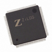
EZ80F93AZ020SG Zilog, EZ80F93AZ020SG Datasheet - Page 163

EZ80F93AZ020SG
Manufacturer Part Number
EZ80F93AZ020SG
Description
IC ACCLAIM MCU 64KB 100LQFP
Manufacturer
Zilog
Series
eZ80® Acclaim!®r
Specifications of EZ80F93AZ020SG
Core Processor
Z8
Core Size
8-Bit
Speed
20MHz
Connectivity
I²C, IrDA, SPI, UART/USART
Peripherals
Brown-out Detect/Reset, POR, WDT
Number Of I /o
24
Program Memory Size
64KB (64K x 8)
Program Memory Type
FLASH
Ram Size
4K x 8
Voltage - Supply (vcc/vdd)
3 V ~ 3.6 V
Oscillator Type
Internal
Operating Temperature
0°C ~ 70°C
Package / Case
100-LQFP
Processor Series
EZ80F93x
Core
eZ80
Data Bus Width
8 bit
Data Ram Size
4 KB
Interface Type
I2C, IrDA, SPI, UART
Maximum Clock Frequency
20 MHz
Number Of Programmable I/os
24
Number Of Timers
6
Operating Supply Voltage
3 V to 3.6 V
Maximum Operating Temperature
+ 70 C
Mounting Style
SMD/SMT
Development Tools By Supplier
eZ80F920200ZCOG
Minimum Operating Temperature
0 C
Lead Free Status / RoHS Status
Lead free / RoHS Compliant
Eeprom Size
-
Data Converters
-
Lead Free Status / Rohs Status
Details
Other names
269-3874
EZ80F93AZ020SG
EZ80F93AZ020SG
Available stocks
Company
Part Number
Manufacturer
Quantity
Price
- Current page: 163 of 261
- Download datasheet (4Mb)
PS015313-0508
set to 1, the I
GCE bit (I2C_SAR[0]) is set to 1.
When the Master Mode Start bit (STA) is set to 1, the I
sends a START condition on the bus when the bus is free. If the STA bit is set to 1 when
the I
repeated START condition is sent. If the STA bit is set to 1 when the I
in SLAVE mode, the I
MASTER mode when the bus is released. The STA bit is automatically cleared after a
START condition is set. Writing a 0 to this bit produces no effect.
If the Master Mode Stop bit (STP) is set to 1 in MASTER mode, a STOP condition is
transmitted on the I
as if a STOP condition is received, but no STOP condition is transmitted. If both STA and
STP bits are set, the I
and then transmit the START condition. The STP bit is cleared automatically. Writing a 0
to this bit produces no effect.
The I
I
set to 1 and the IEN bit is also set, an interrupt is generated. When IFLG is set by the I
the Low period of the I
When a 0 is written to IFLG, the interrupt is cleared and the I
When the I
acknowledge clock pulse on the I
•
•
•
When AAK is cleared to 0, a NACK is sent when a data byte is received in MASTER or
SLAVE mode. If AAK is cleared to 0 in the Slave Transmitter mode, the byte in the
I2C_DR register is assumed to be the final byte. After this byte is transmitted, the I
block enter states
its slave address unless AAK is set. See
2
C states is entered. The only state that does not set the IFLG bit is state F8h. If IFLG is
Either the whole of a 7-bit slave address or the first or second byte of a 10-bit slave
address is received
The general call address is received and the General Call Enable bit in I2C_SAR is set
to 1
A data byte is received while in MASTER or SLAVE modes
2
2
C module is already in MASTER mode and one or more bytes are transmitted, then a
C Interrupt Flag (IFLG) is set to 1 automatically when any of 30 of the possible 31
2
C Acknowledge bit (AAK) is set to 1, an Acknowledge is sent during the
2
C responds to calls to its slave address and to the general call address if the
C8h
2
C bus. If the STP bit is set to 1 in slave move, the I
2
, then returns to the idle state. The I
2
C block first transmits the STOP condition (if in MASTER mode)
2
C completes the data transfer in SLAVE mode and then enters
C bus clock line is stretched and the data transfer is suspended.
2
C bus if:
Table 87
on page 157.
2
C enters MASTER mode and
2
C module does not respond to
2
C clock line is released.
Product Specification
2
I2C Serial I/O Interface
2
C block is accessed
C module operates
2
C
2
C,
156
Related parts for EZ80F93AZ020SG
Image
Part Number
Description
Manufacturer
Datasheet
Request
R

Part Number:
Description:
Communication Controllers, ZILOG INTELLIGENT PERIPHERAL CONTROLLER (ZIP)
Manufacturer:
Zilog, Inc.
Datasheet:

Part Number:
Description:
KIT DEV FOR Z8 ENCORE 16K TO 64K
Manufacturer:
Zilog
Datasheet:

Part Number:
Description:
KIT DEV Z8 ENCORE XP 28-PIN
Manufacturer:
Zilog
Datasheet:

Part Number:
Description:
DEV KIT FOR Z8 ENCORE 8K/4K
Manufacturer:
Zilog
Datasheet:

Part Number:
Description:
KIT DEV Z8 ENCORE XP 28-PIN
Manufacturer:
Zilog
Datasheet:

Part Number:
Description:
DEV KIT FOR Z8 ENCORE 4K TO 8K
Manufacturer:
Zilog
Datasheet:

Part Number:
Description:
CMOS Z8 microcontroller. ROM 16 Kbytes, RAM 256 bytes, speed 16 MHz, 32 lines I/O, 3.0V to 5.5V
Manufacturer:
Zilog, Inc.
Datasheet:

Part Number:
Description:
Low-cost microcontroller. 512 bytes ROM, 61 bytes RAM, 8 MHz
Manufacturer:
Zilog, Inc.
Datasheet:

Part Number:
Description:
Z8 4K OTP Microcontroller
Manufacturer:
Zilog, Inc.
Datasheet:

Part Number:
Description:
CMOS SUPER8 ROMLESS MCU
Manufacturer:
Zilog, Inc.
Datasheet:

Part Number:
Description:
SL1866 CMOSZ8 OTP Microcontroller
Manufacturer:
Zilog, Inc.
Datasheet:

Part Number:
Description:
SL1866 CMOSZ8 OTP Microcontroller
Manufacturer:
Zilog, Inc.
Datasheet:

Part Number:
Description:
OTP (KB) = 1, RAM = 125, Speed = 12, I/O = 14, 8-bit Timers = 2, Comm Interfaces Other Features = Por, LV Protect, Voltage = 4.5-5.5V
Manufacturer:
Zilog, Inc.
Datasheet:

Part Number:
Description:
Manufacturer:
Zilog, Inc.
Datasheet:


