HD64F3644DV Renesas Electronics America, HD64F3644DV Datasheet - Page 147
HD64F3644DV
Manufacturer Part Number
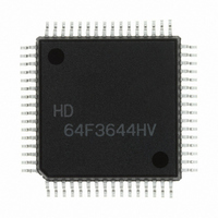
HD64F3644DV
Description
IC H8/3644 MCU FLASH 64QFP
Manufacturer
Renesas Electronics America
Series
H8® H8/300Lr
Datasheet
1.HD64F3644HV.pdf
(551 pages)
Specifications of HD64F3644DV
Core Processor
H8/300L
Core Size
8-Bit
Speed
8MHz
Connectivity
SCI
Peripherals
PWM, WDT
Number Of I /o
53
Program Memory Size
32KB (32K x 8)
Program Memory Type
FLASH
Ram Size
1K x 8
Voltage - Supply (vcc/vdd)
2.7 V ~ 5.5 V
Data Converters
A/D 8x8b
Oscillator Type
Internal
Operating Temperature
-40°C ~ 85°C
Package / Case
64-QFP
Lead Free Status / RoHS Status
Lead free / RoHS Compliant
Eeprom Size
-
Available stocks
Company
Part Number
Manufacturer
Quantity
Price
Company:

Part Number:
HD64F3644DV
Manufacturer:
Renesas Electronics America
Quantity:
10 000


7. If the TEST pin input level is changed (e.g. from 0 V to 5 V to 12 V) during a reset (while a
8. Regarding 12 V application to the FV
Note: * For further information on V
6.6.2
When set to user program mode, the H8/3644F, H8/3643F, or H8/3642AF can program and erase
its flash memory by executing a user program. Therefore, on-board reprogramming of the on-chip
flash memory can be carried out by providing on-board means of supplying V
data, and storing an on-board reprogramming program in part of the program area.
User program mode is selected by applying 12 V to the FV
accessed, during a reset or after confirming that a reset has been performed properly (after the
reset is released).
The flash memory cannot be read while being programmed or erased, so the on-board
reprogramming program or flash memory reprogramming routine should be transferred to the
RAM area, and on-board reprogramming executed in that area.
Boot mode can be exited by driving the reset pin low, then releasing 12 V application to the
TEST pin and FV
release the reset.
However, external pin settings must not be changed during boot mode execution.
Note that the boot mode state is not maintained if 12 V application to the TEST pin is released
while in boot mode.
Also, if a watchdog timer reset occurs in this boot mode state, the built-in boot program will be
restarted without clearing the MCU’s internal mode state.
low level is being input at the RES pin), port states will change as a result of the change of
MCU operating mode. Therefore, care must be taken to make pin settings to prevent these pins
from becoming output signal pins during a reset, and to prevent collision with signals outside
the MCU.
exceed the maximum rating of 13 V.
Also, be sure to connect bypass capacitors to the FV
User Program Mode
6.9, Flash Memory Programming and Erasing Precautions.
PP
pin at least 10 system clock cycles later, and setting the TEST pin to V
PP
PP
application, release, and cut-off, see note 5 in section
and TEST pins, insure that peak overshoot does not
PP
Rev. 6.00 Sep 12, 2006 page 125 of 526
and TEST pins.
PP
pin when flash memory is not being
PP
REJ09B0326-0600
and programming
Section 6 ROM
SS
to
Related parts for HD64F3644DV
Image
Part Number
Description
Manufacturer
Datasheet
Request
R

Part Number:
Description:
(HD64 Series) Hitachi Single-Chip Microcomputer
Manufacturer:
Hitachi Semiconductor
Datasheet:

Part Number:
Description:
KIT STARTER FOR M16C/29
Manufacturer:
Renesas Electronics America
Datasheet:

Part Number:
Description:
KIT STARTER FOR R8C/2D
Manufacturer:
Renesas Electronics America
Datasheet:

Part Number:
Description:
R0K33062P STARTER KIT
Manufacturer:
Renesas Electronics America
Datasheet:

Part Number:
Description:
KIT STARTER FOR R8C/23 E8A
Manufacturer:
Renesas Electronics America
Datasheet:

Part Number:
Description:
KIT STARTER FOR R8C/25
Manufacturer:
Renesas Electronics America
Datasheet:

Part Number:
Description:
KIT STARTER H8S2456 SHARPE DSPLY
Manufacturer:
Renesas Electronics America
Datasheet:

Part Number:
Description:
KIT STARTER FOR R8C38C
Manufacturer:
Renesas Electronics America
Datasheet:

Part Number:
Description:
KIT STARTER FOR R8C35C
Manufacturer:
Renesas Electronics America
Datasheet:

Part Number:
Description:
KIT STARTER FOR R8CL3AC+LCD APPS
Manufacturer:
Renesas Electronics America
Datasheet:
Part Number:
Description:
KIT STARTER FOR RX610
Manufacturer:
Renesas Electronics America
Datasheet:

Part Number:
Description:
KIT STARTER FOR R32C/118
Manufacturer:
Renesas Electronics America
Datasheet:

Part Number:
Description:
KIT DEV RSK-R8C/26-29
Manufacturer:
Renesas Electronics America
Datasheet:

Part Number:
Description:
KIT STARTER FOR SH7124
Manufacturer:
Renesas Electronics America
Datasheet:

Part Number:
Description:
KIT STARTER FOR H8SX/1622
Manufacturer:
Renesas Electronics America
Datasheet: