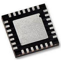
WM8986GECO/V Wolfson Microelectronics, WM8986GECO/V Datasheet - Page 23

WM8986GECO/V
Manufacturer Part Number
WM8986GECO/V
Description
Audio Amplifiers Class D Headphone DAC + Line Out
Manufacturer
Wolfson Microelectronics
Datasheet
1.WM8986GECOV.pdf
(88 pages)
Specifications of WM8986GECO/V
Product
Class-D
Output Power
40 mW
Thd Plus Noise
- 86 dB
Operating Supply Voltage
1.71 V to 3.6 V, 2.5 V to 3.6 V
Maximum Operating Temperature
+ 85 C
Mounting Style
SMD/SMT
Audio Load Resistance
16 Ohms
Minimum Operating Temperature
- 40 C
Output Signal Type
Differential
Supply Voltage (max)
3.6 V
Supply Voltage (min)
1.71 V, 2.5 V
Output Type
Differential
Package / Case
QFN-28
Lead Free Status / RoHS Status
Lead free / RoHS Compliant
Production Data
INPUT SIGNAL PATH
w
Selection of the mode is via the MODE pin. In 2 wire mode, the address of the device is fixed as
0011010.
CLOCKING SCHEMES
WM8986 offers the normal audio DAC clocking scheme operation, where 256fs MCLK is provided to
the DAC. A flexible clock divider allows the 256fs DAC clock to be generated from a range of input
clock frequencies, for example, 256fs, 384fs, 512fs and 768fs.
A PLL is included which may be used to generate these clocks in the event that they are not
available from the system controller. This PLL can accept a range of common input clock
frequencies between 8MHz and 50MHz to generate high quality audio clocks. If this PLL is not
required for generation of these clocks, it can be reconfigured to generate alternative clocks which
may then be output on the GPIO1 pin and used elsewhere in the system; available in 2-wire control
mode only.
POWER CONTROL
The design of the WM8986 has given much attention to power consumption without compromising
performance. The WM8986 operates at low analog and digital supply voltages, and includes the
ability to power off any unused parts of the circuitry under software control. It also includes standby
and power off modes.
The WM8986 has a number of flexible analogue inputs. There are two input channels, Left and
Right, each of which consists of an input PGA stage followed by a boost/mix stage which drives into
the output mixers. Each input path has three input pins which can be configured in a variety of ways
to accommodate single-ended, pseudo-differential or dual differential microphones. There are two
auxiliary input pins which can be fed into to the input boost/mix stage as well as driving into the
output path. An additional signal path exists from the output of the boost/mix stage into the output
left/right mixers.
MICROPHONE INPUTS
The WM8986 can accommodate a variety of microphone configurations including single ended and
pseudo-differential inputs. The inputs to the left differential input PGA are LIN and LIP. The inputs to
the right differential input PGA are RIN and RIP.
PD, Rev 4.1, June 2009
WM8986
23


