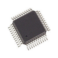
SLXT332QE.G2 Cortina Systems Inc, SLXT332QE.G2 Datasheet - Page 37

SLXT332QE.G2
Manufacturer Part Number
SLXT332QE.G2
Description
Manufacturer
Cortina Systems Inc
Datasheet
1.SLXT332QE.G2.pdf
(45 pages)
Specifications of SLXT332QE.G2
Operating Supply Voltage (typ)
5V
Screening Level
Industrial
Mounting
Surface Mount
Operating Supply Voltage (min)
4.75V
Operating Supply Voltage (max)
5.25V
Operating Temperature (min)
-40C
Operating Temperature (max)
85C
Lead Free Status / RoHS Status
Not Compliant
Available stocks
Company
Part Number
Manufacturer
Quantity
Price
Company:
Part Number:
SLXT332QE.G2
Manufacturer:
ICS
Quantity:
427
LXT332
Datasheet
249075, Revision 2.0
26 June 2007
Table 13
Table 14
Cortina Systems
Input leakage current
Three
Input pull down current (MCLK)
TTIP/TRING leakage current
1. Total power dissipation includes the device power consumption and load power dissipation while driving a 75
2. Functionality of pins depends on mode.
3. Output drivers will output CMOS logic levels into CMOS loads.
4. Except for MCLK, RTIP0, RRING0, RTIP1, and RRING1.
5. Applies to QFP pins 8, 11, 23 & 26; PLCC pins 14, 17, 29 & 32
AMI output pulse
amplitudes
Transmit amplitude variation with supply
Recommended output load at TTIP and TRING
Driver output impedance
Jitter added by the
transmitter
Jitter added by the
transmitter
Output power levels
DS1 2 kHz BW
Positive to negative pulse imbalance
Receive input impedance
Sensitivity below DSX
Loss of signal threshold
Data decision threshold
1. Input signal to TCLK is jitter
2. Circuit attenuates jitter at 20 dB/decade above the corner frequency.
3. Not production tested, but guaranteed by design and other correlation models.
secondary side. The T1 test circuit is a 100
without series resistors.
-
state leakage current
1
1
Parameter
Electrical Characteristics (Over Recommended Operating Conditions)
(Sheet 2 of 2)
Analog Specifications (Over Recommended Operating Conditions)
(Sheet 1 of 2)
®
LXT332 Dual T1/E1 Line Interface Unit with Crystal-less Jitter Attenuation
3
4
Parameter
(max 6 dB cable attenuation)
3
2
5
-
free.
DSX
E1 (120 Ω)
E1 (75 Ω)
10 Hz
8 kHz
10 Hz
Broad Band
20 Hz – 100 kHz
@772 kHz
@ 1544 kHz
(0 dB = 2.4 V)
DSX
E1
-
-
1
1
Sym
-
-
-
3
Isl
Itr
Ill
8 kHz
40 kHz
40 kHz
Ω
3
3
3
Min
line load connected to the driver outputs via a 1:1.15 turns ratio transformer
0
0
–
Typ
2.13
12.6
13.6
–
–
–
–
Min
500
-
2.4
2.7
60
43
–
–
–
29
–
–
–
–
–
–
–
–
Max
±10
±10
100
1.2
0.005
0.015
2.37
0.02
0.03
Typ
3.0
3.0
0.3
75
40
50
70
1
3
–
–
–
–
–
–
Units
mA
μA
μA
μA
0.025
0.025
Max
2.61
0.01
0.05
0.05
17.9
3.6
3.3
2.5
0.5
10
77
57
–
–
–
–
–
–
In tri
% peak
% peak
Units
-
dBm
mV
state and power down modes
kΩ
dB
dB
dB
UI
UI
UI
UI
UI
%
V
V
V
Ω
Ω
V
Test Conditions
6.0 Test Specifications
measured at the DSX
measured at line side
measured at line side
@ 772 kHz
T1 Jitter based
E1 Jitter Band
referenced to power in
2 kHz band at 772 kHz
Test Conditions
Ω
load on the
Page 37


