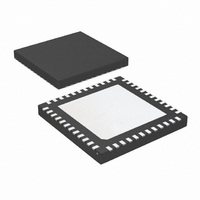
LMK03200ISQE/NOPB National Semiconductor, LMK03200ISQE/NOPB Datasheet - Page 3

LMK03200ISQE/NOPB
Manufacturer Part Number
LMK03200ISQE/NOPB
Description
IC CLOCK CONDITIONER PREC 48-LLP
Manufacturer
National Semiconductor
Type
Clock Conditionerr
Datasheet
1.LMK03200ISQENOPB.pdf
(40 pages)
Specifications of LMK03200ISQE/NOPB
Pll
Yes
Input
Clock
Output
LVDS, LVPECL
Number Of Circuits
1
Ratio - Input:output
1:9
Differential - Input:output
Yes/Yes
Frequency - Max
1.296GHz
Divider/multiplier
Yes/No
Voltage - Supply
3.15 V ~ 3.45 V
Operating Temperature
-40°C ~ 85°C
Mounting Type
Surface Mount
Package / Case
48-LLP
Frequency-max
1.296GHz
Lead Free Status / RoHS Status
Lead free / RoHS Compliant
Other names
LMK03200ISQETR
Available stocks
Company
Part Number
Manufacturer
Quantity
Price
Company:
Part Number:
LMK03200ISQE/NOPB
Manufacturer:
NSC
Quantity:
72
General Description .............................................................................................................................. 1
Target Applications ............................................................................................................................... 1
Features .............................................................................................................................................. 1
System Diagram ................................................................................................................................... 1
Functional Block Diagram ...................................................................................................................... 2
Connection Diagram ............................................................................................................................. 5
Pin Descriptions .................................................................................................................................. 6
Absolute Maximum Ratings .................................................................................................................... 7
Recommended Operating Conditions ..................................................................................................... 7
Package Thermal Resistance ................................................................................................................. 7
Electrical Characteristics ....................................................................................................................... 8
Serial Data Timing Diagram ................................................................................................................ 11
Typical Performance Characteristics ..................................................................................................... 13
1.0 Functional Description .................................................................................................................... 14
2.0 General Programming Information ................................................................................................... 18
Charge Pump Current Specification Definitions ................................................................................ 12
1.1 BIAS PIN .............................................................................................................................. 14
1.2 LDO BYPASS ........................................................................................................................ 14
1.3 OSCILLATOR INPUT PORT (OSCin, OSCin*) ........................................................................... 14
1.4 LOW NOISE, FULLY INTEGRATED VCO ................................................................................. 14
1.5 LVDS/LVPECL OUTPUTS ...................................................................................................... 14
1.6 GLOBAL CLOCK OUTPUT SYNCHRONIZATION ...................................................................... 15
1.7 CLKout OUTPUT STATES ...................................................................................................... 15
1.8 GLOBAL OUTPUT ENABLE AND LOCK DETECT ..................................................................... 15
1.9 POWER ON RESET ............................................................................................................... 15
1.10 DIGITAL LOCK DETECT ....................................................................................................... 16
1.11 CLKout DELAYS .................................................................................................................. 16
1.12 GLOBAL DELAYS ................................................................................................................ 17
1.13 VCO DIVIDER BYPASS MODE .............................................................................................. 17
1.14 0-DELAY MODE .................................................................................................................. 17
2.1 Recommended Programming Sequence, without 0-Delay Mode ................................................... 18
2.2 Recommended Programing Sequence, with 0-Delay Mode .......................................................... 18
2.3 Recommended Programming Sequence, bypassing VCO divider ................................................. 20
2.4 Register R0 to R7 ................................................................................................................... 24
2.5 Register R8 ........................................................................................................................... 26
2.6 Register R9 ........................................................................................................................... 26
2.7 Register R11 ......................................................................................................................... 27
2.8 Register R13 ......................................................................................................................... 27
2.9 Register R14 ......................................................................................................................... 27
2.10 REGISTER R15 ................................................................................................................... 28
2.2.1 0-Delay Mode Example 1 .............................................................................................. 19
2.2.2 0-Delay Mode Example 2 .............................................................................................. 19
2.3.1 VCO divider bypass example ......................................................................................... 20
2.4.1 Reset bit -- Reset device to power on defaults .................................................................. 24
2.4.2 DLD_MODE2 bit -- Digital Lock Detect Mode 2 ................................................................. 24
2.4.3 0_DELAY_MODE bit -- Activate 0-Delay Mode ................................................................. 25
2.4.4 FB_MUX [1:0] -- Feedback Mux ..................................................................................... 25
2.4.5 VCO_MUX [1:0] -- VCO Mux .......................................................................................... 25
2.4.6 CLKoutX_MUX [1:0] -- Clock Output Multiplexers .............................................................. 25
2.4.7 CLKoutX_DIV [7:0] -- Clock Output Dividers ..................................................................... 26
2.4.8 CLKoutX_DLY [3:0] -- Clock Output Delays ...................................................................... 26
2.4.9 CLKoutX_EN bit -- Clock Output Enables ........................................................................ 26
2.6.1 Vboost bit -- Voltage Boost ............................................................................................ 26
2.7.1 DIV4 -- High Phase Detector Frequencies and Lock Detect ................................................ 27
2.8.1 VCO_C3_C4_LF [3:0] -- Value for Internal Loop Filter Capacitors C3 and C4 ....................... 27
2.8.2 VCO_R3_LF [2:0] -- Value for Internal Loop Filter Resistor R3 ............................................ 27
2.8.3 VCO_R4_LF [2:0] -- Value for Internal Loop Filter Resistor R4 ............................................ 27
2.8.4 OSCin_FREQ [7:0] -- Oscillator Input Calibration Adjustment ............................................. 27
2.9.1 PLL_R [11:0] -- R Divider Value ...................................................................................... 27
2.9.2 PLL_MUX[3:0] -- Multiplexer Control for LD Pin ................................................................ 28
2.9.3 POWERDOWN bit -- Device Power Down ....................................................................... 28
2.9.4 EN_CLKout_Global bit -- Global Clock Output Enable ....................................................... 28
2.9.5 EN_Fout bit -- Fout port enable ...................................................................................... 28
2.9.6 PLL_R_DLY [3:0] - Global Skew Adjust, Lag .................................................................... 28
Table of Contents
3
www.national.com


