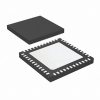
LMK03200ISQE/NOPB National Semiconductor, LMK03200ISQE/NOPB Datasheet - Page 38

LMK03200ISQE/NOPB
Manufacturer Part Number
LMK03200ISQE/NOPB
Description
IC CLOCK CONDITIONER PREC 48-LLP
Manufacturer
National Semiconductor
Type
Clock Conditionerr
Datasheet
1.LMK03200ISQENOPB.pdf
(40 pages)
Specifications of LMK03200ISQE/NOPB
Pll
Yes
Input
Clock
Output
LVDS, LVPECL
Number Of Circuits
1
Ratio - Input:output
1:9
Differential - Input:output
Yes/Yes
Frequency - Max
1.296GHz
Divider/multiplier
Yes/No
Voltage - Supply
3.15 V ~ 3.45 V
Operating Temperature
-40°C ~ 85°C
Mounting Type
Surface Mount
Package / Case
48-LLP
Frequency-max
1.296GHz
Lead Free Status / RoHS Status
Lead free / RoHS Compliant
Other names
LMK03200ISQETR
Available stocks
Company
Part Number
Manufacturer
Quantity
Price
Company:
Part Number:
LMK03200ISQE/NOPB
Manufacturer:
NSC
Quantity:
72
www.national.com
3.10 DIFFERENTIAL VOLTAGE MEASUREMENT
TERMINOLOGY
The differential voltage of a differential signal can be de-
scribed by two different definitions causing confusion when
reading datasheets or communicating with other engineers.
This section will address the measurement and description of
a differential signal so that the reader will be able to under-
stand and discern between the two different definitions when
used.
The first definition used to describe a differential signal is the
absolute value of the voltage potential between the inverting
and non-inverting signal. The symbol for this first measure-
ment is typically V
voltage is being described.
The second definition used to describe a differential signal is
to measure the potential of the non-inverting signal with re-
spect to the inverting signal. The symbol for this second
measurement is V
in the IC does this signal exist with respect to ground, it only
exists in reference to its differential pair. V
directly by oscilloscopes with floating references, otherwise
this value can be calculated as twice the value of V
scribed in the first description.
Figure 19
side-by-side for inputs and outputs respectively. The V
V
verting and inverting signals toggle between with respect to
ground. V
verting signal is considered the reference, the non-inverting
signal voltage potential is now increasing and decreasing
above and below the non-inverting reference. Thus the peak-
to-peak voltage of the differential signal can be measured.
Hence V
often defined as volts peak-to-peak (V
OD
definitions show V
ID
and
SS
and V
input and output definitions show that if the in-
Figure 20
OD
ID
SS
or V
are often defined as volts (V) and V
and is a calculated parameter. Nowhere
A
OD
illustrate the two different definitions
and V
depending on if an input or output
B
DC levels that the non-in-
PP
).
SS
can be measured
OD
as de-
ID
SS
and
is
38
Refer to application note AN-912 Common Data Transmis-
sion Parameters and their Definitions for more information.
FIGURE 19. Two Different Definitions for Differential
FIGURE 20. Two Different Definitions for Differential
Output Signals
Input Signals
30088775
30088774


