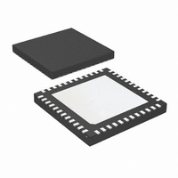
LMK03200ISQE/NOPB National Semiconductor, LMK03200ISQE/NOPB Datasheet - Page 4

LMK03200ISQE/NOPB
Manufacturer Part Number
LMK03200ISQE/NOPB
Description
IC CLOCK CONDITIONER PREC 48-LLP
Manufacturer
National Semiconductor
Type
Clock Conditionerr
Datasheet
1.LMK03200ISQENOPB.pdf
(40 pages)
Specifications of LMK03200ISQE/NOPB
Pll
Yes
Input
Clock
Output
LVDS, LVPECL
Number Of Circuits
1
Ratio - Input:output
1:9
Differential - Input:output
Yes/Yes
Frequency - Max
1.296GHz
Divider/multiplier
Yes/No
Voltage - Supply
3.15 V ~ 3.45 V
Operating Temperature
-40°C ~ 85°C
Mounting Type
Surface Mount
Package / Case
48-LLP
Frequency-max
1.296GHz
Lead Free Status / RoHS Status
Lead free / RoHS Compliant
Other names
LMK03200ISQETR
Available stocks
Company
Part Number
Manufacturer
Quantity
Price
Company:
Part Number:
LMK03200ISQE/NOPB
Manufacturer:
NSC
Quantity:
72
www.national.com
3.0 Application Information ................................................................................................................... 31
Physical Dimensions ........................................................................................................................... 39
Ordering Information ........................................................................................................................... 39
FIGURE 1. Frequency Calibration Routine Flowchart ........................................................................................ 14
FIGURE 2. SYNC* Timing Diagram ............................................................................................................. 15
FIGURE 3. Digital Lock Detect Flowchart ...................................................................................................... 16
FIGURE 4. Global Lead and Lag ................................................................................................................. 17
FIGURE 5. Outline of 0-delay mode programming sequence ............................................................................... 17
FIGURE 6. Typical Application ................................................................................................................... 31
FIGURE 7. Loop Filter ............................................................................................................................. 32
FIGURE 8. Differential LVDS Operation, DC Coupling ....................................................................................... 34
FIGURE 9. Differential LVPECL Operation, DC Coupling ................................................................................... 35
FIGURE 10. Differential LVPECL Operation, DC Coupling, Thevenin Equivalent ....................................................... 35
FIGURE 11. Differential LVDS Operation, AC Coupling ..................................................................................... 35
FIGURE 12. Differential LVPECL Operation, AC Coupling, Thevenin Equivalent ....................................................... 35
FIGURE 13. Single-Ended LVPECL Operation, DC Coupling .............................................................................. 36
FIGURE 14. Single-Ended LVPECL Operation, DC Coupling, Thevenin Equivalent ................................................... 36
FIGURE 15. Single-Ended LVPECL Operation, AC Coupling .............................................................................. 36
FIGURE 16. Single-Ended Sine Wave Input ................................................................................................... 36
FIGURE 17. Differential Sine Wave Input ...................................................................................................... 37
FIGURE 18. Recommended OSCin Power for Operation with a Sine Wave Input ...................................................... 37
FIGURE 19. Two Different Definitions for Differential Input Signals ....................................................................... 38
FIGURE 20. Two Different Definitions for Differential Output Signals ..................................................................... 38
3.1 SYSTEM LEVEL DIAGRAM .................................................................................................... 31
3.2 BIAS PIN .............................................................................................................................. 31
3.3 LDO BYPASS ........................................................................................................................ 31
3.4 LOOP FILTER ....................................................................................................................... 32
3.5 CURRENT CONSUMPTION / POWER DISSIPATION CALCULATIONS ....................................... 33
3.6 THERMAL MANAGEMENT ..................................................................................................... 34
3.7 TERMINATION AND USE OF CLOCK OUTPUTS (DRIVERS) ..................................................... 34
3.8 OSCin INPUT ........................................................................................................................ 36
3.9 MORE THAN EIGHT OUTPUTS WITH AN LMK03200 FAMILY DEVICE ....................................... 37
3.10 DIFFERENTIAL VOLTAGE MEASUREMENT TERMINOLOGY .................................................. 38
2.10.1 PLL_N [17:0] -- PLL N Divider ...................................................................................... 28
2.10.2 VCO_DIV [3:0] -- VCO Divider ...................................................................................... 29
2.10.3 PLL_CP_GAIN [1:0] -- PLL Charge Pump Gain .............................................................. 29
2.10.4 PLL_N_DLY [3:0] - Global Skew Adjust, Lead ................................................................. 30
3.7.1 Termination for DC Coupled Differential Operation ............................................................ 34
3.7.2 Termination for AC Coupled Differential Operation ............................................................ 35
3.7.3 Termination for Single-Ended Operation .......................................................................... 36
3.7.4 Conversion to LVCMOS Outputs .................................................................................... 36
List of Figures
4


