MPC8349ECVVAGDB Freescale Semiconductor, MPC8349ECVVAGDB Datasheet - Page 86
MPC8349ECVVAGDB
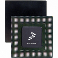
Manufacturer Part Number
MPC8349ECVVAGDB
Description
IC MPU POWERQUICC II 672-TBGA
Manufacturer
Freescale Semiconductor
Datasheet
1.MPC8349EVVAJFB.pdf
(87 pages)
Specifications of MPC8349ECVVAGDB
Processor Type
MPC83xx PowerQUICC II Pro 32-Bit
Speed
400MHz
Voltage
1.2V
Mounting Type
Surface Mount
Package / Case
672-TBGA
For Use With
MPC8349E-MITX-GP - KIT REFERENCE PLATFORM MPC8349EMPC8349E-MITXE - BOARD REFERENCE FOR MPC8349MPC8349EA-MDS-PB - KIT MODULAR DEV SYSTEM MPC8349E
Lead Free Status / RoHS Status
Lead free / RoHS Compliant
Features
-
Available stocks
Company
Part Number
Manufacturer
Quantity
Price
Company:

Part Number:
MPC8349ECVVAGDB
Manufacturer:
FREESCALE
Quantity:
8
Company:
Part Number:
MPC8349ECVVAGDB
Manufacturer:
Freescale Semiconductor
Quantity:
10 000


Document Revision History
86
Number
Rev.
3
2
1
0
MPC8349EA PowerQUICC II Pro Integrated Host Processor Hardware Specifications, Rev. 12
11/2006
8/2006
4/2006
3/2006
Date
Initial public release.
• Updated note in introduction.
• In the features list in Section 1, “Overview,” updated DDR data rate to show 400 MHz for DDR2
•
• In Section 23, “Ordering Information,” replicated note from document introduction.
• Changed all references to revision 2.0 silicon to revision 3.0 silicon.
• Changed VIH minimum value in Table 40, “JTAG Interface DC Electrical Characteristics,” to
• In Table 44, “PCI DC Electrical Characteristics,” changed high-level input voltage values to min
• Updated DDR2 I/O power values in Table 5, “MPC8347EA Typical I/O Power Dissipation.”
• In Table 66, “Suggested PLL Configurations,” deleted reference-number rows 902 and 703.
• Removed Table 20, “Timing Parameters for DDR2-400.”
• Changed ADDR/CMD to ADDR/CMD/MODT in Table 9, “DDR and DDR2 SDRAM Output AC
• Changed Min and Max values for V
• In Table 55, “MPC8349EA (TBGA) Pinout Listing,” and Table 52, “MPC8347EA (PBGA) Pinout
• Table 55, “MPC8349EA (TBGA) Pinout Listing,” in row AVDD3 changed power supply from
for TBGA parts for silicon 3.x and 400 MHz for DDR2 for TBGA parts for silicon 3.x.
OV
= 2 and max = OV
Timing Specifications,” rows 2 and 3, and in Figure 2, “DDR SDRAM Output Timing Diagram.
Characteristics.”
Listing,” modified rows for MDICO and MDIC1 signals and added note ‘It is recommended that
MDICO be tied to GRD using an 18 Ω resistor and MCIC1 be tied to DDR power using an 18 Ω
resistor.’
“AVDD3” to ‘—.’
DD
Table 68. Document Revision History (continued)
– 0.3.
DD
+ 0.3; changed low-level input voltage values to min = (–0.3) and max = 0.8.
Substantive Change(s)
IH
and VIL in Table 40Table 44,“PCI DC Electrical
Freescale Semiconductor
Related parts for MPC8349ECVVAGDB
Image
Part Number
Description
Manufacturer
Datasheet
Request
R

Part Number:
Description:
BOARD REFERENCE FOR MPC8349
Manufacturer:
Freescale Semiconductor
Datasheet:

Part Number:
Description:
KIT REFERENCE PLATFORM MPC8349E
Manufacturer:
Freescale Semiconductor
Datasheet:
Part Number:
Description:
KIT MODULAR DEV SYSTEM MPC8349E
Manufacturer:
Freescale Semiconductor
Datasheet:

Part Number:
Description:
MCU, MPU & DSP Development Tools PROCESSR BD MPC8349E
Manufacturer:
Freescale Semiconductor
Part Number:
Description:
MCU, MPU & DSP Development Tools KIT FOR MPC8349E BDS
Manufacturer:
Freescale Semiconductor

Part Number:
Description:
Manufacturer:
Freescale Semiconductor, Inc
Datasheet:
Part Number:
Description:
Manufacturer:
Freescale Semiconductor, Inc
Datasheet:
Part Number:
Description:
Manufacturer:
Freescale Semiconductor, Inc
Datasheet:
Part Number:
Description:
Manufacturer:
Freescale Semiconductor, Inc
Datasheet:
Part Number:
Description:
Manufacturer:
Freescale Semiconductor, Inc
Datasheet:
Part Number:
Description:
Manufacturer:
Freescale Semiconductor, Inc
Datasheet:
Part Number:
Description:
Manufacturer:
Freescale Semiconductor, Inc
Datasheet:
Part Number:
Description:
Manufacturer:
Freescale Semiconductor, Inc
Datasheet:
Part Number:
Description:
Manufacturer:
Freescale Semiconductor, Inc
Datasheet:
Part Number:
Description:
Manufacturer:
Freescale Semiconductor, Inc
Datasheet: