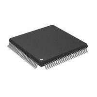
AD9882AKSTZ-100 Analog Devices Inc, AD9882AKSTZ-100 Datasheet - Page 2

AD9882AKSTZ-100
Manufacturer Part Number
AD9882AKSTZ-100
Description
IC INTERFACE/DVI 100MHZ 100LQFP
Manufacturer
Analog Devices Inc
Datasheet
1.AD9882KSTZ-100.pdf
(40 pages)
Specifications of AD9882AKSTZ-100
Applications
Video
Interface
Analog, DVI
Voltage - Supply
3.15 V ~ 3.45 V
Package / Case
100-LQFP
Mounting Type
Surface Mount
Supply Voltage Range
3.15V To 3.45V, 2.2V To 3.45V
Operating Temperature Range
0°C To +70°C
Digital Ic Case Style
LQFP
No. Of Pins
100
Msl
MSL 3 - 168 Hours
Update Rate
140MSPS
Bandwidth
300MHz
Rohs Compliant
Yes
Lead Free Status / RoHS Status
Lead free / RoHS Compliant
Available stocks
Company
Part Number
Manufacturer
Quantity
Price
Company:
Part Number:
AD9882AKSTZ-100
Manufacturer:
AD
Quantity:
1 200
Company:
Part Number:
AD9882AKSTZ-100
Manufacturer:
ADI
Quantity:
352
Company:
Part Number:
AD9882AKSTZ-100
Manufacturer:
Analog Devices Inc
Quantity:
10 000
Part Number:
AD9882AKSTZ-100
Manufacturer:
ADI/亚德诺
Quantity:
20 000
AD9882A
TABLE OF CONTENTS
Specifications............................................................................................3
Absolute Maximum Ratings ..................................................................6
Pin Configuration and Function Descriptions....................................7
Theory of Operation: Interface Detection .........................................12
Theory of Operation and Design Guide: Analog Interface.............13
Timing: Analog Interface .....................................................................17
Theory of Operation: Digital Interface...............................................19
REVISION HISTORY
10/04—Revision 0: Initial Version
Explanation of Test Levels..................................................................6
ESD Caution ........................................................................................6
Pin Descriptions of Shared Pins between Analog and Digital
Interfaces ..............................................................................................8
Serial Port (2-Wire) ............................................................................8
Data Outputs........................................................................................8
Pin Function Detail: Analog Interface .............................................9
Power Supply .....................................................................................10
Active Interface Detection and Selection.......................................12
Power Management ..........................................................................12
General Description..........................................................................13
Input Signal Handling ......................................................................13
Hsync and Vsync Inputs ..................................................................13
Serial Control Port ............................................................................13
Output Signal Handling ...................................................................13
Clamping ............................................................................................13
Gain and Offset Control...................................................................14
Sync-on-Green (SOG)......................................................................15
Clock Generation ..............................................................................15
Timing Diagrams ..............................................................................18
Digital Interface Pin Descriptions ..................................................19
Capturing the Encoded Data...........................................................20
Data Frames .......................................................................................20
Rev. 0 | Page 2 of 40
2-Wire Serial Register Map ..................................................................23
2-Wire Serial Control Register Detail.................................................26
Sync Processing Engine ........................................................................35
PCB Layout Recommendations...........................................................36
Outline Dimensions ..............................................................................38
Special Characters .............................................................................20
Channel Resynchronization.............................................................20
Data Decoder .....................................................................................20
HDCP..................................................................................................20
General Timing Diagrams: Digital Interface.................................22
Timing Mode Diagrams: Digital Interface ....................................22
Chip Identification ............................................................................26
PLL Divider Control .........................................................................26
Clamp Timing....................................................................................27
Hsync Output Pulse Width..............................................................27
Input Gain ..........................................................................................27
Input Offset ........................................................................................27
2-Wire Serial Control Port...............................................................32
Sync Slicer...........................................................................................35
Sync Separator ...................................................................................35
Analog Interface Inputs ....................................................................36
Digital Interface Inputs.....................................................................36
Power Supply Bypassing ...................................................................36
PLL ......................................................................................................37
Outputs: Data and Clocks ................................................................37
Digital Inputs .....................................................................................37
Voltage Reference ..............................................................................37
Ordering Guide..................................................................................38


