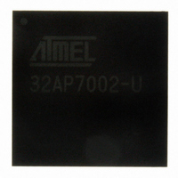
AT32AP7002-CTUT Atmel, AT32AP7002-CTUT Datasheet - Page 48

AT32AP7002-CTUT
Manufacturer Part Number
AT32AP7002-CTUT
Description
IC MCU 32BIT AVR32 196-CBGA
Manufacturer
Atmel
Series
AVR®32 AP7r
Specifications of AT32AP7002-CTUT
Core Processor
AVR
Core Size
32-Bit
Speed
150MHz
Connectivity
EBI/EMI, I²C, MMC, PS2, SPI, SSC, UART/USART, USB
Peripherals
AC'97, DMA, I²C, LCD, POR, PWM, WDT
Number Of I /o
85
Program Memory Type
ROMless
Ram Size
32K x 8
Voltage - Supply (vcc/vdd)
1.65 V ~ 1.95 V
Data Converters
D/A 2x16b
Oscillator Type
Internal
Operating Temperature
-40°C ~ 85°C
Package / Case
196-CBGA
Data Bus Width
32 bit
Data Ram Size
32 KB
Interface Type
I2C, JTAG, PS2, SPI, SSC, UART, USART, USB
Maximum Clock Frequency
150 MHz
Number Of Timers
3
Maximum Operating Temperature
+ 85 C
Mounting Style
SMD/SMT
Minimum Operating Temperature
- 40 C
On-chip Dac
16 bit, 2 Channel
Package
196CTBGA
Device Core
AVR32
Family Name
AT32
Maximum Speed
150 MHz
Operating Supply Voltage
1.8|3.3 V
For Use With
ATAVRONEKIT - KIT AVR/AVR32 DEBUGGER/PROGRMMRATNGW100 - KIT AVR32 NETWORK GATEWAYATSTK1000 - KIT STARTER FOR AVR32AP7000
Lead Free Status / RoHS Status
Lead free / RoHS Compliant
Eeprom Size
-
Program Memory Size
-
Lead Free Status / Rohs Status
Details
Available stocks
Company
Part Number
Manufacturer
Quantity
Price
- Current page: 48 of 896
- Download datasheet (13Mb)
7.7.1.16
Register Name: CONFIG
Access Type: Read/Write
• OIM: Output Insertion Mode
The OIM bit specifies the semantics of the OUTd output pixel address parameter to the pico(s)v(mul/mac) instructions. The
OIM together with the output pixel address parameter specify which of the 12 output bytes (OUTn) of the OUTPIXn regis-
ters will be updated with the results from the VMUs.
See
Table 7-2.
• ISM: Input Selection Mode
T h e I S M f i e l d s p e c i f i e s t h e s e m a n t i c s o f t h e i n p u t p i x e l a d d r e s s p a r a m e t e r s I N x , I N y a n d I N z t o t h e
pico(s)v(mul/mac) instructions. Together with the three input pixel addresses the ISM field specifies to the Input Pixel
Selector which of the input pixels (INn) that should be selected as inputs to the
32054F–AVR32–09/09
OIM
0
1
Section 7.6 ”Output Pixel Inserter” on page 30
31
23
15
7
-
-
-
Mode
Packed Insertion Mode
Planar Insertion Mode
PICO Configuration Register
Output Insertion Modes
OFFSET_FRAC_BITS
30
22
14
6
-
-
-
Description
{OUTPIX0, OUTPIX1, OUTPIX2} is treated as one large register containing 4 sequential 24-
bit pixel triplets. The DST_ADR field specifies which of the sequential triplets will be updated.
OUT(d*3 + 0) ← Scaled and saturated output from VMU0
OUT(d*3 + 1) ← Scaled and saturated output from VMU1
OUT(d*3 + 2) ← Scaled and saturated output from VMU2
Each of the OUTPIXn registers will get one of the resulting pixels. The triplet address
specifies what byte in each of the OUTPIXn registers the results will be written to.
OUT(d + 0) ← Scaled and saturated output from VMU0
OUT(d+ 4) ← Scaled and saturated output from VMU1
OUT(d + 8) ← Scaled and saturated output from VMU2
29
21
13
5
-
-
-
for a description of the Output Pixel Inserter.
28
20
12
Table 7-2 on page 48
4
-
-
-
27
19
11
3
-
-
-
describes the different Output Insertion Modes.
VMUs.Table 7-3 on page 49
OIM
COEFF_FRAC_BITS
26
18
10
2
-
-
AT32AP7002
25
17
9
1
-
-
ISM
describes the
24
16
8
0
-
-
48
Related parts for AT32AP7002-CTUT
Image
Part Number
Description
Manufacturer
Datasheet
Request
R

Part Number:
Description:
DEV KIT FOR AVR/AVR32
Manufacturer:
Atmel
Datasheet:

Part Number:
Description:
INTERVAL AND WIPE/WASH WIPER CONTROL IC WITH DELAY
Manufacturer:
ATMEL Corporation
Datasheet:

Part Number:
Description:
Low-Voltage Voice-Switched IC for Hands-Free Operation
Manufacturer:
ATMEL Corporation
Datasheet:

Part Number:
Description:
MONOLITHIC INTEGRATED FEATUREPHONE CIRCUIT
Manufacturer:
ATMEL Corporation
Datasheet:

Part Number:
Description:
AM-FM Receiver IC U4255BM-M
Manufacturer:
ATMEL Corporation
Datasheet:

Part Number:
Description:
Monolithic Integrated Feature Phone Circuit
Manufacturer:
ATMEL Corporation
Datasheet:

Part Number:
Description:
Multistandard Video-IF and Quasi Parallel Sound Processing
Manufacturer:
ATMEL Corporation
Datasheet:

Part Number:
Description:
High-performance EE PLD
Manufacturer:
ATMEL Corporation
Datasheet:

Part Number:
Description:
8-bit Flash Microcontroller
Manufacturer:
ATMEL Corporation
Datasheet:

Part Number:
Description:
2-Wire Serial EEPROM
Manufacturer:
ATMEL Corporation
Datasheet:


