DF2378BVFQ35WV Renesas Electronics America, DF2378BVFQ35WV Datasheet - Page 26
DF2378BVFQ35WV
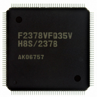
Manufacturer Part Number
DF2378BVFQ35WV
Description
IC H8S/2378 MCU FLASH 144-QFP
Manufacturer
Renesas Electronics America
Series
H8® H8S/2300r
Datasheet
1.YR0K42378FC000BA.pdf
(1208 pages)
Specifications of DF2378BVFQ35WV
Core Processor
H8S/2000
Core Size
16-Bit
Speed
35MHz
Connectivity
I²C, IrDA, SCI, SmartCard
Peripherals
DMA, POR, PWM, WDT
Number Of I /o
97
Program Memory Size
512KB (512K x 8)
Program Memory Type
FLASH
Ram Size
32K x 8
Voltage - Supply (vcc/vdd)
3 V ~ 3.6 V
Data Converters
A/D 16x10b; D/A 6x8b
Oscillator Type
Internal
Operating Temperature
-40°C ~ 85°C
Package / Case
144-QFP
For Use With
EDK2378 - DEV EVAL KIT FOR H8S/2378
Lead Free Status / RoHS Status
Lead free / RoHS Compliant
Eeprom Size
-
Available stocks
Company
Part Number
Manufacturer
Quantity
Price
Company:

Part Number:
DF2378BVFQ35WV
Manufacturer:
Renesas Electronics America
Quantity:
10 000


2.8
2.9
Section 3 MCU Operating Modes ....................................................................... 71
3.1
3.2
3.3
3.4
Section 4 Exception Handling ............................................................................. 93
4.1
4.2
4.3
4.4
4.5
4.6
4.7
4.8
Section 5 Interrupt Controller............................................................................ 103
5.1
5.2
5.3
Rev.7.00 Mar. 18, 2009 page xxiv of lxvi
REJ09B0109-0700
2.7.9
Processing States.................................................................................................................. 68
Usage Note........................................................................................................................... 69
2.9.1
Operating Mode Selection.................................................................................................... 71
Register Descriptions ........................................................................................................... 72
3.2.1
3.2.2
Operating Mode Descriptions .............................................................................................. 75
3.3.1
3.3.2
3.3.3
3.3.4
3.3.5
3.3.6
3.3.7
Memory Map in Each Operating Mode ............................................................................... 78
Exception Handling Types and Priority ............................................................................... 93
Exception Sources and Exception Vector Table .................................................................. 93
Reset..................................................................................................................................... 95
4.3.1
4.3.2
4.3.3
Trace Exception Handling.................................................................................................... 98
Interrupt Exception Handling............................................................................................... 98
Trap Instruction Exception Handling................................................................................... 99
Stack Status after Exception Handling............................................................................... 100
Usage Note......................................................................................................................... 101
Features .............................................................................................................................. 103
Input/Output Pins ............................................................................................................... 105
Register Descriptions ......................................................................................................... 105
5.3.1
5.3.2
5.3.3
5.3.4
Effective Address Calculation ................................................................................ 66
Note on Bit Manipulation Instructions.................................................................... 69
Mode Control Register (MDCR) ............................................................................ 72
System Control Register (SYSCR) ......................................................................... 72
Mode 1 .................................................................................................................... 75
Mode 2 .................................................................................................................... 75
Mode 3 .................................................................................................................... 75
Mode 4 .................................................................................................................... 75
Mode 5 .................................................................................................................... 76
Mode 7 .................................................................................................................... 76
Pin Functions .......................................................................................................... 77
Reset Exception Handling....................................................................................... 95
Interrupts after Reset............................................................................................... 97
On-Chip Peripheral Functions after Reset Release ................................................. 97
Interrupt Control Register (INTCR)...................................................................... 106
Interrupt Priority Registers A to K (IPRA to IPRK) ............................................. 106
IRQ Enable Register (IER) ................................................................................... 108
IRQ Sense Control Registers H and L (ISCRH, ISCRL)...................................... 110
Related parts for DF2378BVFQ35WV
Image
Part Number
Description
Manufacturer
Datasheet
Request
R

Part Number:
Description:
KIT STARTER FOR M16C/29
Manufacturer:
Renesas Electronics America
Datasheet:

Part Number:
Description:
KIT STARTER FOR R8C/2D
Manufacturer:
Renesas Electronics America
Datasheet:

Part Number:
Description:
R0K33062P STARTER KIT
Manufacturer:
Renesas Electronics America
Datasheet:

Part Number:
Description:
KIT STARTER FOR R8C/23 E8A
Manufacturer:
Renesas Electronics America
Datasheet:

Part Number:
Description:
KIT STARTER FOR R8C/25
Manufacturer:
Renesas Electronics America
Datasheet:

Part Number:
Description:
KIT STARTER H8S2456 SHARPE DSPLY
Manufacturer:
Renesas Electronics America
Datasheet:

Part Number:
Description:
KIT STARTER FOR R8C38C
Manufacturer:
Renesas Electronics America
Datasheet:

Part Number:
Description:
KIT STARTER FOR R8C35C
Manufacturer:
Renesas Electronics America
Datasheet:

Part Number:
Description:
KIT STARTER FOR R8CL3AC+LCD APPS
Manufacturer:
Renesas Electronics America
Datasheet:
Part Number:
Description:
KIT STARTER FOR RX610
Manufacturer:
Renesas Electronics America
Datasheet:

Part Number:
Description:
KIT STARTER FOR R32C/118
Manufacturer:
Renesas Electronics America
Datasheet:

Part Number:
Description:
KIT DEV RSK-R8C/26-29
Manufacturer:
Renesas Electronics America
Datasheet:

Part Number:
Description:
KIT STARTER FOR SH7124
Manufacturer:
Renesas Electronics America
Datasheet:

Part Number:
Description:
KIT STARTER FOR H8SX/1622
Manufacturer:
Renesas Electronics America
Datasheet:

Part Number:
Description:
KIT DEV FOR SH7203
Manufacturer:
Renesas Electronics America
Datasheet: