DF2378BVFQ35WV Renesas Electronics America, DF2378BVFQ35WV Datasheet - Page 887
DF2378BVFQ35WV
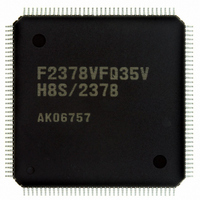
Manufacturer Part Number
DF2378BVFQ35WV
Description
IC H8S/2378 MCU FLASH 144-QFP
Manufacturer
Renesas Electronics America
Series
H8® H8S/2300r
Datasheet
1.YR0K42378FC000BA.pdf
(1208 pages)
Specifications of DF2378BVFQ35WV
Core Processor
H8S/2000
Core Size
16-Bit
Speed
35MHz
Connectivity
I²C, IrDA, SCI, SmartCard
Peripherals
DMA, POR, PWM, WDT
Number Of I /o
97
Program Memory Size
512KB (512K x 8)
Program Memory Type
FLASH
Ram Size
32K x 8
Voltage - Supply (vcc/vdd)
3 V ~ 3.6 V
Data Converters
A/D 16x10b; D/A 6x8b
Oscillator Type
Internal
Operating Temperature
-40°C ~ 85°C
Package / Case
144-QFP
For Use With
EDK2378 - DEV EVAL KIT FOR H8S/2378
Lead Free Status / RoHS Status
Lead free / RoHS Compliant
Eeprom Size
-
Available stocks
Company
Part Number
Manufacturer
Quantity
Price
Company:

Part Number:
DF2378BVFQ35WV
Manufacturer:
Renesas Electronics America
Quantity:
10 000


17.7.3
Adding capacitance results in coupling with GND, and therefore noise in GND may adversely
affect absolute precision. Be sure to make the connection to an electrically stable GND such as
AVss.
Care is also required to insure that filter circuits do not communicate with digital signals on the
mounting board, so acting as antennas.
17.7.4
If conditions shown below are not met, the reliability of the device may be adversely affected.
• Analog input voltage range
• Relation between AVcc, AVss and Vcc, Vss
• Vref setting range
17.7.5
In board design, digital circuitry and analog circuitry should be as mutually isolated as possible,
and layout in which digital circuit signal lines and analog circuit signal lines cross or are in close
proximity should be avoided as far as possible. Failure to do so may result in incorrect operation
of the analog circuitry due to inductance, adversely affecting A/D conversion values.
Also, digital circuitry must be isolated from the analog input signals (AN0 to AN15), analog
reference power supply (Vref), and analog power supply (AVcc) by the analog ground (AVss).
Also, the analog ground (AVss) should be connected at one point to a stable digital ground (Vss)
on the board.
17.7.6
A protection circuit connected to prevent damage due to an abnormal voltage such as an excessive
surge at the analog input pins (AN0 to AN15) should be connected between AVcc and AVss as
shown in figure 17.7. Also, the bypass capacitors connected to AVcc and the filter capacitor
connected to AN0 to AN15 must be connected to AVss.
The voltage applied to analog input pin ANn during A/D conversion should be in the range
AVss ≤ AVn ≤ Vref.
As the relationship between AVcc, AVss and Vcc, Vss, set AVcc ≥ Vcc and AVss = Vss. If
the A/D converter is not used, the AVcc and AVss pins must not be left open.
The reference voltage at the Vref pin should be set in the range Vref ≤ AVcc.
Influences on Absolute Precision
Setting Range of Analog Power Supply and Other Pins
Notes on Board Design
Notes on Noise Countermeasures
Rev.7.00 Mar. 18, 2009 page 819 of 1136
Section 17 A/D Converter
REJ09B0109-0700
Related parts for DF2378BVFQ35WV
Image
Part Number
Description
Manufacturer
Datasheet
Request
R

Part Number:
Description:
KIT STARTER FOR M16C/29
Manufacturer:
Renesas Electronics America
Datasheet:

Part Number:
Description:
KIT STARTER FOR R8C/2D
Manufacturer:
Renesas Electronics America
Datasheet:

Part Number:
Description:
R0K33062P STARTER KIT
Manufacturer:
Renesas Electronics America
Datasheet:

Part Number:
Description:
KIT STARTER FOR R8C/23 E8A
Manufacturer:
Renesas Electronics America
Datasheet:

Part Number:
Description:
KIT STARTER FOR R8C/25
Manufacturer:
Renesas Electronics America
Datasheet:

Part Number:
Description:
KIT STARTER H8S2456 SHARPE DSPLY
Manufacturer:
Renesas Electronics America
Datasheet:

Part Number:
Description:
KIT STARTER FOR R8C38C
Manufacturer:
Renesas Electronics America
Datasheet:

Part Number:
Description:
KIT STARTER FOR R8C35C
Manufacturer:
Renesas Electronics America
Datasheet:

Part Number:
Description:
KIT STARTER FOR R8CL3AC+LCD APPS
Manufacturer:
Renesas Electronics America
Datasheet:
Part Number:
Description:
KIT STARTER FOR RX610
Manufacturer:
Renesas Electronics America
Datasheet:

Part Number:
Description:
KIT STARTER FOR R32C/118
Manufacturer:
Renesas Electronics America
Datasheet:

Part Number:
Description:
KIT DEV RSK-R8C/26-29
Manufacturer:
Renesas Electronics America
Datasheet:

Part Number:
Description:
KIT STARTER FOR SH7124
Manufacturer:
Renesas Electronics America
Datasheet:

Part Number:
Description:
KIT STARTER FOR H8SX/1622
Manufacturer:
Renesas Electronics America
Datasheet:

Part Number:
Description:
KIT DEV FOR SH7203
Manufacturer:
Renesas Electronics America
Datasheet: