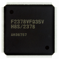
DF2378BVFQ35WV Renesas Electronics America, DF2378BVFQ35WV Datasheet - Page 62

DF2378BVFQ35WV
Manufacturer Part Number
DF2378BVFQ35WV
Description
IC H8S/2378 MCU FLASH 144-QFP
Manufacturer
Renesas Electronics America
Series
H8® H8S/2300r
Datasheet
1.YR0K42378FC000BA.pdf
(1208 pages)
Specifications of DF2378BVFQ35WV
Core Processor
H8S/2000
Core Size
16-Bit
Speed
35MHz
Connectivity
I²C, IrDA, SCI, SmartCard
Peripherals
DMA, POR, PWM, WDT
Number Of I /o
97
Program Memory Size
512KB (512K x 8)
Program Memory Type
FLASH
Ram Size
32K x 8
Voltage - Supply (vcc/vdd)
3 V ~ 3.6 V
Data Converters
A/D 16x10b; D/A 6x8b
Oscillator Type
Internal
Operating Temperature
-40°C ~ 85°C
Package / Case
144-QFP
For Use With
EDK2378 - DEV EVAL KIT FOR H8S/2378
Lead Free Status / RoHS Status
Lead free / RoHS Compliant
Eeprom Size
-
Available stocks
Company
Part Number
Manufacturer
Quantity
Price
Company:
Part Number:
DF2378BVFQ35WV
Manufacturer:
Renesas Electronics America
Quantity:
10 000
- Current page: 62 of 1208
- Download datasheet (8Mb)
Table 6.2
Table 6.3
Table 6.4
Table 6.5
Table 6.6
Table 6.7
Table 6.8
Table 6.9
Table 6.10
Table 6.11
Table 6.12
Table 6.13
Section 7 DMA Controller (DMAC)................................................................. 279
Table 7.1
Table 7.2
Table 7.3
Table 7.4
Table 7.5
Table 7.6
Table 7.7
Table 7.8
Table 7.9
Table 7.10
Table 7.11
Table 7.12
Section 8 EXDMA Controller (EXDMAC) ...................................................... 359
Table 8.1
Table 8.2
Table 8.3
Table 8.4
Section 9 Data Transfer Controller (DTC) ........................................................ 425
Table 9.1
Table 9.2
Table 9.3
Table 9.4
Table 9.5
Rev.7.00 Mar. 18, 2009 page lx of lxvi
REJ09B0109-0700
Bus Specifications for Each Area (Basic Bus Interface) ......................................... 173
Data Buses Used and Valid Strobes ........................................................................ 178
Relation between Settings of Bits RMTS2 to RMTS0 and DRAM Space.............. 191
Relation between Settings of Bits MXC2 to MXC0 and Address Multiplexing ..... 192
DRAM Interface Pins.............................................................................................. 193
Relation between Settings of Bits RMTS2 to RMTS0
and Synchronous DRAM Space.............................................................................. 216
Relation between Settings of Bits MXC2 to MXC0 and Address Multiplexing ..... 217
Synchronous DRAM Interface Pins ........................................................................ 219
Setting CAS Latency ............................................................................................... 222
Idle Cycles in Mixed Accesses to Normal Space and DRAM Continuous
Synchronous DRAM Space..................................................................................... 264
Pin States in Idle Cycle ........................................................................................... 268
Pin States in Bus Released State ............................................................................. 271
Pin Configuration .................................................................................................... 281
Short Address Mode and Full Address Mode (Channel 0)...................................... 282
DMAC Activation Sources ..................................................................................... 307
DMAC Transfer Modes........................................................................................... 310
Register Functions in Sequential Mode................................................................... 312
Register Functions in Idle Mode ............................................................................. 315
Register Functions in Repeat Mode ........................................................................ 317
Register Functions in Single Address Mode ........................................................... 320
Register Functions in Normal Mode ....................................................................... 323
Register Functions in Block Transfer Mode............................................................ 326
DMAC Channel Priority Order ............................................................................... 347
Interrupt Sources and Priority Order ....................................................................... 353
Pin Configuration .................................................................................................... 361
EXDMAC Transfer Modes ..................................................................................... 374
EXDMAC Channel Priority Order.......................................................................... 390
Interrupt Sources and Priority Order ....................................................................... 420
Relationship between Activation Sources and DTCER Clearing............................ 432
Interrupt Sources, DTC Vector Addresses, and Corresponding DTCEs ................. 435
Chain Transfer Conditions ...................................................................................... 439
Register Function in Normal Mode......................................................................... 440
Register Function in Repeat Mode .......................................................................... 441
Related parts for DF2378BVFQ35WV
Image
Part Number
Description
Manufacturer
Datasheet
Request
R

Part Number:
Description:
KIT STARTER FOR M16C/29
Manufacturer:
Renesas Electronics America
Datasheet:

Part Number:
Description:
KIT STARTER FOR R8C/2D
Manufacturer:
Renesas Electronics America
Datasheet:

Part Number:
Description:
R0K33062P STARTER KIT
Manufacturer:
Renesas Electronics America
Datasheet:

Part Number:
Description:
KIT STARTER FOR R8C/23 E8A
Manufacturer:
Renesas Electronics America
Datasheet:

Part Number:
Description:
KIT STARTER FOR R8C/25
Manufacturer:
Renesas Electronics America
Datasheet:

Part Number:
Description:
KIT STARTER H8S2456 SHARPE DSPLY
Manufacturer:
Renesas Electronics America
Datasheet:

Part Number:
Description:
KIT STARTER FOR R8C38C
Manufacturer:
Renesas Electronics America
Datasheet:

Part Number:
Description:
KIT STARTER FOR R8C35C
Manufacturer:
Renesas Electronics America
Datasheet:

Part Number:
Description:
KIT STARTER FOR R8CL3AC+LCD APPS
Manufacturer:
Renesas Electronics America
Datasheet:

Part Number:
Description:
KIT STARTER FOR RX610
Manufacturer:
Renesas Electronics America
Datasheet:

Part Number:
Description:
KIT STARTER FOR R32C/118
Manufacturer:
Renesas Electronics America
Datasheet:

Part Number:
Description:
KIT DEV RSK-R8C/26-29
Manufacturer:
Renesas Electronics America
Datasheet:

Part Number:
Description:
KIT STARTER FOR SH7124
Manufacturer:
Renesas Electronics America
Datasheet:

Part Number:
Description:
KIT STARTER FOR H8SX/1622
Manufacturer:
Renesas Electronics America
Datasheet:

Part Number:
Description:
KIT DEV FOR SH7203
Manufacturer:
Renesas Electronics America
Datasheet:


