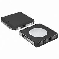
P80C592FFA/00,512 NXP Semiconductors, P80C592FFA/00,512 Datasheet - Page 36

P80C592FFA/00,512
Manufacturer Part Number
P80C592FFA/00,512
Description
IC 80C51 MCU 8BIT ROMLESS 68PLCC
Manufacturer
NXP Semiconductors
Series
80Cr
Datasheet
1.P80C592FFA00512.pdf
(108 pages)
Specifications of P80C592FFA/00,512
Program Memory Type
ROMless
Package / Case
68-PLCC
Core Processor
8051
Core Size
8-Bit
Speed
16MHz
Connectivity
CAN, EBI/EMI, UART/USART
Peripherals
DMA, POR, PWM, WDT
Number Of I /o
48
Ram Size
512 x 8
Voltage - Supply (vcc/vdd)
4.5 V ~ 5.5 V
Data Converters
A/D 8x10b
Oscillator Type
Internal
Operating Temperature
-40°C ~ 85°C
Processor Series
P80C5x
Core
80C51
Data Bus Width
8 bit
Data Ram Size
512 B
Interface Type
CAN/UART
Maximum Clock Frequency
16 MHz
Number Of Programmable I/os
40
Number Of Timers
3
Maximum Operating Temperature
+ 85 C
Mounting Style
SMD/SMT
3rd Party Development Tools
PK51, CA51, A51, ULINK2
Minimum Operating Temperature
- 40 C
On-chip Adc
8-ch x 10-bit
Cpu Family
80C
Device Core
80C51
Device Core Size
8b
Frequency (max)
16MHz
Program Memory Size
Not Required
Total Internal Ram Size
512Byte
# I/os (max)
40
Number Of Timers - General Purpose
3
Operating Supply Voltage (typ)
5V
Operating Supply Voltage (max)
5.5V
Operating Supply Voltage (min)
4.5V
Instruction Set Architecture
CISC
Operating Temp Range
-40C to 85C
Operating Temperature Classification
Industrial
Mounting
Surface Mount
Pin Count
68
Package Type
PLCC
Lead Free Status / RoHS Status
Lead free / RoHS Compliant
Eeprom Size
-
Program Memory Size
-
Lead Free Status / Rohs Status
Compliant
Other names
568-1241-5
935086530512
P80C592FFAA
935086530512
P80C592FFAA
Available stocks
Company
Part Number
Manufacturer
Quantity
Price
Company:
Part Number:
P80C592FFA/00,512
Manufacturer:
ON
Quantity:
300
Company:
Part Number:
P80C592FFA/00,512
Manufacturer:
NXP Semiconductors
Quantity:
10 000
Philips Semiconductors
Notes to the description of the CMR bits
1. The RX0/RX1 Active bits, if being read, reflect the status of the respective switches (see Fig.16). It is recommended
2. The Wake-Up Mode bit should be set at the same time as the Sleep bit. The differential wake up mode is useful if
3. The CAN-controller will enter sleep mode, if the Sleep bit is set HIGH (sleep) there is no bus activity and no interrupt
4. This command bit is used to acknowledge the Data Overrun condition signalled by the Data Overrun status bit.
5. After reading the contents of the Receive Buffer (RBF0 or RBF1) the CPU must release this buffer by setting Release
6. The Abort Transmission bit is used when the CPU requires the suspension of the previously requested transmission,
7. If the Transmission Request bit was set HIGH in a previous command, it cannot be cancelled by setting the
Table 35 Combination of bits RX0A and RX1A (see Fig.16)
1996 Jun 27
8-bit microcontroller with on-chip CAN
to change the switches only during the reset state (Reset Request = HIGH).
both bus wires are fully functioning; it minimizes the amount of wake ups due to noise. The single ended wake up
mode is recommended if a wake up must be possible even if one bus wire is already or may become disturbed
(see Fig.16).
is pending. The CAN-controller will wake up after the Sleep bit is set LOW (wake up) or when there is bus activity.
On wake up, a Wake-Up Interrupt (see Section 13.5.6) is generated (see also Chapter 15). A CAN-controller which
is sleeping and then awaken by bus activity will not be able to receive this message until it detects a Bus-Free signal
(see Section 13.6.9.6). The Sleep bit, if read, reflects the status of the CAN-controller.
Command is given only after releasing both receive buffers. The stored messages have to be rejected. The
command bit is set simultaneously with setting of the Release Receive Buffer command bit the second time.
Receive Buffer bit HIGH (released). This may result in another message becoming immediately available.
To prevent the RRB command being executed only once, the minimum wait time between two successive RRB
commands is 3 system clock cycles (t
e.g. to transmit an urgent message. A transmission already in progress is not stopped. In order to see if the original
message had been either transmitted successfully or aborted, the Transmission Complete Status bit should be
checked. This should be done after the Transmit Buffer Access bit has been set HIGH (released) or a Transmit
Interrupt has been generated (see Section 13.5.6).
Transmission Request bit LOW (absent). Cancellation of the requested transmission may be performed by setting
the Abort Transmission bit HIGH (present).
RX0A
1
1
0
0
CONTROL
SCL
RX1A
, see Section 13.5.9).
1
0
1
0
36
1
CRX0
CRX0
2
RX0
AV
DD
No action
Product specification
1
CRX1
CRX1
2
RX1
P8xC592
AV
DD


