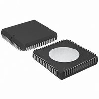
P80C592FFA/00,512 NXP Semiconductors, P80C592FFA/00,512 Datasheet - Page 53

P80C592FFA/00,512
Manufacturer Part Number
P80C592FFA/00,512
Description
IC 80C51 MCU 8BIT ROMLESS 68PLCC
Manufacturer
NXP Semiconductors
Series
80Cr
Datasheet
1.P80C592FFA00512.pdf
(108 pages)
Specifications of P80C592FFA/00,512
Program Memory Type
ROMless
Package / Case
68-PLCC
Core Processor
8051
Core Size
8-Bit
Speed
16MHz
Connectivity
CAN, EBI/EMI, UART/USART
Peripherals
DMA, POR, PWM, WDT
Number Of I /o
48
Ram Size
512 x 8
Voltage - Supply (vcc/vdd)
4.5 V ~ 5.5 V
Data Converters
A/D 8x10b
Oscillator Type
Internal
Operating Temperature
-40°C ~ 85°C
Processor Series
P80C5x
Core
80C51
Data Bus Width
8 bit
Data Ram Size
512 B
Interface Type
CAN/UART
Maximum Clock Frequency
16 MHz
Number Of Programmable I/os
40
Number Of Timers
3
Maximum Operating Temperature
+ 85 C
Mounting Style
SMD/SMT
3rd Party Development Tools
PK51, CA51, A51, ULINK2
Minimum Operating Temperature
- 40 C
On-chip Adc
8-ch x 10-bit
Cpu Family
80C
Device Core
80C51
Device Core Size
8b
Frequency (max)
16MHz
Program Memory Size
Not Required
Total Internal Ram Size
512Byte
# I/os (max)
40
Number Of Timers - General Purpose
3
Operating Supply Voltage (typ)
5V
Operating Supply Voltage (max)
5.5V
Operating Supply Voltage (min)
4.5V
Instruction Set Architecture
CISC
Operating Temp Range
-40C to 85C
Operating Temperature Classification
Industrial
Mounting
Surface Mount
Pin Count
68
Package Type
PLCC
Lead Free Status / RoHS Status
Lead free / RoHS Compliant
Eeprom Size
-
Program Memory Size
-
Lead Free Status / Rohs Status
Compliant
Other names
568-1241-5
935086530512
P80C592FFAA
935086530512
P80C592FFAA
Available stocks
Company
Part Number
Manufacturer
Quantity
Price
Company:
Part Number:
P80C592FFA/00,512
Manufacturer:
ON
Quantity:
300
Company:
Part Number:
P80C592FFA/00,512
Manufacturer:
NXP Semiconductors
Quantity:
10 000
Philips Semiconductors
13.5.19.3 Time Segment 2 (TSEG2)
This time segment provides:
TSEG2 is programmable from 1 to 8 system clock cycles
(see Section 13.5.10).
13.5.19.4 Synchronisation Jump Width (SJW)
SJW defines the maximum number of clock cycles (t
period may be reduced or increased by one
resynchronization. SJW is programmable from 1 to 4
system clock cycles, see Section 13.5.2.
13.5.19.5 Propagation Delay Time (t
The Propagation Delay Time is:
t
13.5.19.6 Bit Timing Restrictions
Restrictions on the configuration of the bit timing are based
on internal processing. The restrictions are:
The three sample mode (SAM = HIGH) has the effect of
introducing a delay of one system clock cycle on the
bus-line. This must be taken into account for the correct
calculation of TSEG1 and TSEG2:
13.5.20 S
Synchronization is performed by a state machine which
compares the incoming edge with its actual bit timing and
adapts the bit timing by hard synchronization or
resynchronization.
1996 Jun 27
t
prop
prop
Additional time at the sample point for calculation of the
subsequent bit levels (e.g. arbitration)
Synchronization buffer segment directly after the
sample point.
t
t
t
t
t
t
8-bit microcontroller with on-chip CAN
TSEG2
TSEG2
TSEG1
TSEG1
TSEG1
TSEG2
is rounded up to the nearest multiple of t
=
2
+
+
YNCHRONIZATION
2t
t
t
t
t
3t
SJW
SEG2
SJW
SJW
input comparator delay
output driver delay
physical bus delay
SCL
SCL
+ t
+ t
.
prop
prop
.
+ 2t
SCL
.
prop
)
SCL
.
SCL
) a
53
This type of synchronization occurs only at the beginning
of a message.
The CAN-controller synchronizes on the first incoming
recessive-to-dominant edge of a message (being the
leading edge of a message's Start-Of-Frame bit;
see Section 13.6.2.
Resynchronization occurs during the transmission of a
message's bit stream to compensate for:
As a result of resynchronization either t
increased by up to a maximum of t
decreased by up to a maximum of t
TSEG1, TSEG2 and SJW are the programmed numerical
values.
The phase error (e) of an edge is given by the position of
the edge relative to SYNCSEG, measured in system clock
cycles (t
The value of the phase error is defined as:
The effect of resynchronization is:
Variations in individual CAN-controller oscillator
frequencies
Changes introduced by switching from one transmitter
to another (e.g. during arbitration).
t
t
e = 0, if the edge occurs within SYNCSEG
e
e
The same as that of a hard synchronization, if the
magnitude of the phase error (e) is less or equal to the
programmed value of t
To increase a bit period by the amount of t
phase error is positive and the magnitude of the phase
error is larger than t
To decrease a bit period by the amount of t
phase error is negative and the magnitude of the phase
error is larger than t
TSEG1
TSEG2
0, if the edge occurs within TSEG1
0, if the edge occurs within TSEG2.
SCL
t
t
SCL
SCL
).
[(TSEG1 + 1) + (SJW + 1)]
[(TSEG2 + 1)
SJW
SJW
SJW
.
(SJW + 1)].
SJW
SJW
Product specification
or t
:
TSEG1
P8xC592
TSEG2
SJW
may be
SJW
may be
, if the
, if the


