MC908QY4ACDWE Freescale Semiconductor, MC908QY4ACDWE Datasheet - Page 40
MC908QY4ACDWE
Manufacturer Part Number
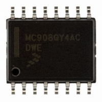
MC908QY4ACDWE
Description
IC MCU 8BIT 4K FLASH 16-SOIC
Manufacturer
Freescale Semiconductor
Series
HC08r
Datasheet
1.MC908QT1ACDWE.pdf
(200 pages)
Specifications of MC908QY4ACDWE
Core Processor
HC08
Core Size
8-Bit
Speed
8MHz
Peripherals
LVD, POR, PWM
Number Of I /o
13
Program Memory Size
4KB (4K x 8)
Program Memory Type
FLASH
Ram Size
128 x 8
Voltage - Supply (vcc/vdd)
2.7 V ~ 5.5 V
Data Converters
A/D 6x10b
Oscillator Type
Internal
Operating Temperature
-40°C ~ 85°C
Package / Case
16-SOIC (0.300", 7.5mm Width)
Processor Series
HC08QY
Core
HC08
Data Bus Width
8 bit
Data Ram Size
128 B
Maximum Clock Frequency
8 MHz
Number Of Programmable I/os
13
Number Of Timers
2
Maximum Operating Temperature
+ 85 C
Mounting Style
SMD/SMT
Development Tools By Supplier
FSICEBASE, M68CBL05AE, DEMO908QB8, DEMO908QC16
Minimum Operating Temperature
- 40 C
On-chip Adc
10 bit, 6 Channel
Lead Free Status / RoHS Status
Lead free / RoHS Compliant
Eeprom Size
-
Connectivity
-
Lead Free Status / Rohs Status
Details
Available stocks
Company
Part Number
Manufacturer
Quantity
Price

Part Number:
MC908QY4ACDWE
Manufacturer:
FREESCALE
Quantity:
20 000
Part Number:
MC908QY4ACDWER
Manufacturer:
FREESCALE
Quantity:
20 000


Analog-to-Digital Converter (ADC10) Module
clocks are too fast, then the clock must be divided to the appropriate frequency. This divider is specified
by the ADIV[1:0] bits and can be divide-by 1, 2, 4, or 8.
3.3.2 Input Select and Pin Control
Only one analog input may be used for conversion at any given time. The channel select bits in ADSCR
are used to select the input signal for conversion.
3.3.3 Conversion Control
Conversions can be performed in either 10-bit mode or 8-bit mode as determined by the MODE bits.
Conversions can be initiated by either a software or hardware trigger. In addition, the ADC10 module can
be configured for low power operation, long sample time, and continuous conversion.
3.3.3.1 Initiating Conversions
A conversion is initiated:
If continuous conversions are enabled a new conversion is automatically initiated after the completion of
the current conversion. In software triggered operation, continuous conversions begin after ADSCR is
written and continue until aborted. In hardware triggered operation, continuous conversions begin after a
hardware trigger event and continue until aborted.
3.3.3.2 Completing Conversions
A conversion is completed when the result of the conversion is transferred into the data result registers,
ADRH and ADRL. This is indicated by the setting of the COCO bit. An interrupt is generated if AIEN is
high at the time that COCO is set.
A blocking mechanism prevents a new result from overwriting previous data in ADRH and ADRL if the
previous data is in the process of being read while in 10-bit mode (ADRH has been read but ADRL has
not). In this case the data transfer is blocked, COCO is not set, and the new result is lost. When a data
transfer is blocked, another conversion is initiated regardless of the state of ADCO (single or continuous
conversions enabled). If single conversions are enabled, this could result in several discarded
conversions and excess power consumption. To avoid this issue, the data registers must not be read after
initiating a single conversion until the conversion completes.
3.3.3.3 Aborting Conversions
Any conversion in progress will be aborted when:
When a conversion is aborted, the contents of the data registers, ADRH and ADRL, are not altered but
continue to be the values transferred after the completion of the last successful conversion. In the case
that the conversion was aborted by a reset, ADRH and ADRL return to their reset states.
40
•
•
•
•
•
•
•
Following a write to ADSCR (with ADCH bits not all 1s) if software triggered operation is selected.
Following a hardware trigger event if hardware triggered operation is selected.
Following the transfer of the result to the data registers when continuous conversion is enabled.
A write to ADSCR occurs (the current conversion will be aborted and a new conversion will be
initiated, if ADCH are not all 1s).
A write to ADCLK occurs.
The MCU is reset.
The MCU enters stop mode with ACLK not enabled.
MC68HC908QYA/QTA Family Data Sheet, Rev. 3
Freescale Semiconductor
Related parts for MC908QY4ACDWE
Image
Part Number
Description
Manufacturer
Datasheet
Request
R

Part Number:
Description:
Manufacturer:
Freescale Semiconductor, Inc
Datasheet:
Part Number:
Description:
Manufacturer:
Freescale Semiconductor, Inc
Datasheet:
Part Number:
Description:
Manufacturer:
Freescale Semiconductor, Inc
Datasheet:
Part Number:
Description:
Manufacturer:
Freescale Semiconductor, Inc
Datasheet:
Part Number:
Description:
Manufacturer:
Freescale Semiconductor, Inc
Datasheet:
Part Number:
Description:
Manufacturer:
Freescale Semiconductor, Inc
Datasheet:
Part Number:
Description:
Manufacturer:
Freescale Semiconductor, Inc
Datasheet:
Part Number:
Description:
Manufacturer:
Freescale Semiconductor, Inc
Datasheet:
Part Number:
Description:
Manufacturer:
Freescale Semiconductor, Inc
Datasheet:
Part Number:
Description:
Manufacturer:
Freescale Semiconductor, Inc
Datasheet:
Part Number:
Description:
Manufacturer:
Freescale Semiconductor, Inc
Datasheet:
Part Number:
Description:
Manufacturer:
Freescale Semiconductor, Inc
Datasheet:
Part Number:
Description:
Manufacturer:
Freescale Semiconductor, Inc
Datasheet:
Part Number:
Description:
Manufacturer:
Freescale Semiconductor, Inc
Datasheet:
Part Number:
Description:
Manufacturer:
Freescale Semiconductor, Inc
Datasheet: