M30840SGP#U5 Renesas Electronics America, M30840SGP#U5 Datasheet - Page 524
M30840SGP#U5
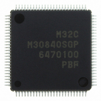
Manufacturer Part Number
M30840SGP#U5
Description
IC M32C/84 MCU ROMLESS 100LQFP
Manufacturer
Renesas Electronics America
Series
M16C™ M32C/80r
Datasheet
1.M30843FWGPU5.pdf
(531 pages)
Specifications of M30840SGP#U5
Core Processor
M32C/80
Core Size
16/32-Bit
Speed
32MHz
Connectivity
CAN, I²C, IEBus, SIO, UART/USART
Peripherals
DMA, PWM, WDT
Number Of I /o
45
Program Memory Type
ROMless
Ram Size
10K x 8
Voltage - Supply (vcc/vdd)
3 V ~ 5.5 V
Data Converters
A/D 10x10b, D/A 2x8b
Oscillator Type
Internal
Operating Temperature
-20°C ~ 85°C
Package / Case
100-LQFP
For Use With
R0K330879S001BE - KIT DEV RSK M32C/87R0K330879S000BE - KIT DEV RSK M32C/87
Lead Free Status / RoHS Status
Lead free / RoHS Compliant
Eeprom Size
-
Program Memory Size
-
Available stocks
Company
Part Number
Manufacturer
Quantity
Price

Part Number:
M30840SGP#U5M30840SGP#U3
Manufacturer:
Renesas Electronics America
Quantity:
10 000


Rev.
REVISION HISTORY
Date
Page
287
290
291
293
294
295
296
297
299
301
311
311
312
315
316
317
318
320
• Table 22.4 Time Measurement Function Specifications Description for the
• Figure 22.14 Time Measurement Function (2) Figure modified
• Figure 22.15 Prescaler Function and Gate Function Letters modified
• Table 22.9 Single-Phase Waveform Output Mode Specifications Setting
• Figure 22.16 Single-Phase Waveform Output Mode Setting value of registers
• Table 22.10 Phase-Delayed Waveform Output Mode Specifications Setting
• Figure 22.17 Phase-Delayed Waveform Output Mode Setting value of regis-
• Table 22.11 SR Waveform Output Mode Specifications Setting value of the
• Figure 22.18 SR Waveform Output Mode Setting value of registers added;
• Figure 22.20 G0CR to G1CR Registers, G0RB to G1RB Registers B14 in the
• Table 22.14 Clock Settings (Communication Unit 1) G1PO0 register setting
• Table 22.15 Registers to be Used and Settings OPOL bit in the GiCR register
• Table 22.16 Pin Settings in Clock Synchronous Serial I/O Mode (Communi-
• Table 22.17 Pin Settings (2) Register column deleted
• Table 22.19 Pin Setttings (3) Registers to be used for P15
• Table 22.20 UART Mode Specifications ISTxD1 and ISRxD1 Polarity Inverse
• Table 22.21 Clock Settings Input from ISCLK1 deleted; note 4 deleted
• Table 22.22 Registers to be Used and Settings UFORM bit function modified;
• Figure 22.31 Transmit Operation Figure modified
• Figure 22.32 Receive Operation Figure modified
• 22.4.3 HDLC Data Processing Mode Description modified
• Table 22.25 HDLC Processing Mode Specifications Transmit Start Condition
• Table 22.28 Registers to be Used and Settings G1PO1 register function
gate function modified
value of the G1PO0 register changed
added; condition added
value of the G1PO0 register changed
ters added; condition added
G1PO0 register changed
condition added
G0RB to G1RBregisters changed to PER bit
value changed
modified
cation Unit 0 and 1)(1) Registers to be used for P7
Register column deteled
function deleted
CSS3 to CSS2 bit functions modified
and Receive Start Condition brought together to Data Processing Start Condition
modified
M32C/84 Group(M32C/84, M32C/84T) Hardware Manual
C-6
Description
Summary
6
and P7
0
7
and 15
deleted
1
deleted;
Related parts for M30840SGP#U5
Image
Part Number
Description
Manufacturer
Datasheet
Request
R

Part Number:
Description:
KIT STARTER FOR M16C/29
Manufacturer:
Renesas Electronics America
Datasheet:

Part Number:
Description:
KIT STARTER FOR R8C/2D
Manufacturer:
Renesas Electronics America
Datasheet:

Part Number:
Description:
R0K33062P STARTER KIT
Manufacturer:
Renesas Electronics America
Datasheet:

Part Number:
Description:
KIT STARTER FOR R8C/23 E8A
Manufacturer:
Renesas Electronics America
Datasheet:

Part Number:
Description:
KIT STARTER FOR R8C/25
Manufacturer:
Renesas Electronics America
Datasheet:

Part Number:
Description:
KIT STARTER H8S2456 SHARPE DSPLY
Manufacturer:
Renesas Electronics America
Datasheet:

Part Number:
Description:
KIT STARTER FOR R8C38C
Manufacturer:
Renesas Electronics America
Datasheet:

Part Number:
Description:
KIT STARTER FOR R8C35C
Manufacturer:
Renesas Electronics America
Datasheet:

Part Number:
Description:
KIT STARTER FOR R8CL3AC+LCD APPS
Manufacturer:
Renesas Electronics America
Datasheet:
Part Number:
Description:
KIT STARTER FOR RX610
Manufacturer:
Renesas Electronics America
Datasheet:

Part Number:
Description:
KIT STARTER FOR R32C/118
Manufacturer:
Renesas Electronics America
Datasheet:

Part Number:
Description:
KIT DEV RSK-R8C/26-29
Manufacturer:
Renesas Electronics America
Datasheet:

Part Number:
Description:
KIT STARTER FOR SH7124
Manufacturer:
Renesas Electronics America
Datasheet:

Part Number:
Description:
KIT STARTER FOR H8SX/1622
Manufacturer:
Renesas Electronics America
Datasheet:

Part Number:
Description:
KIT DEV FOR SH7203
Manufacturer:
Renesas Electronics America
Datasheet: