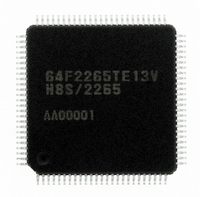
DF2265TE13V Renesas Electronics America, DF2265TE13V Datasheet - Page 35

DF2265TE13V
Manufacturer Part Number
DF2265TE13V
Description
IC H8S/2265 MCU FLASH 100TQFP
Manufacturer
Renesas Electronics America
Series
H8® H8S/2200r
Specifications of DF2265TE13V
Core Processor
H8S/2000
Core Size
16-Bit
Speed
13MHz
Connectivity
I²C, SCI, SmartCard
Peripherals
LCD, POR, PWM, WDT
Number Of I /o
67
Program Memory Size
128KB (128K x 8)
Program Memory Type
FLASH
Ram Size
4K x 8
Voltage - Supply (vcc/vdd)
3 V ~ 5.5 V
Data Converters
A/D 10x10b, D/A 2x8b
Oscillator Type
Internal
Operating Temperature
-20°C ~ 75°C
Package / Case
100-TQFP, 100-VQFP
Lead Free Status / RoHS Status
Lead free / RoHS Compliant
Eeprom Size
-
Available stocks
Company
Part Number
Manufacturer
Quantity
Price
Company:
Part Number:
DF2265TE13V
Manufacturer:
Renesas Electronics America
Quantity:
10 000
- Current page: 35 of 712
- Download datasheet (5Mb)
20.4 Input/Output Pins .............................................................................................................. 511
20.5 Register Descriptions ........................................................................................................ 511
20.6 On-Board Programming Modes........................................................................................ 518
20.7 Flash Memory Emulation in RAM ................................................................................... 522
20.8 Flash Memory Programming/Erasing ............................................................................... 524
20.9 Program/Erase Protection ................................................................................................. 529
20.10 Interrupt Handling when Programming/Erasing Flash Memory....................................... 530
20.11 Programmer Mode ............................................................................................................ 530
20.12 Power-Down States for Flash Memory............................................................................. 532
20.13 Flash Memory Programming and Erasing Precautions ..................................................... 533
20.14 Note on Switching from F-ZTAT Version to Masked ROM Version .............................. 538
Section 21 Clock Pulse Generator .....................................................................539
21.1 Register Descriptions ........................................................................................................ 540
21.2 System Clock Oscillator.................................................................................................... 543
21.3 Duty Adjustment Circuit................................................................................................... 547
21.4 Medium-Speed Clock Divider .......................................................................................... 547
21.5 Bus Master Clock Selection Circuit .................................................................................. 547
21.6 Subclock Oscillator ........................................................................................................... 548
20.5.1 Flash Memory Control Register 1 (FLMCR1)..................................................... 512
20.5.2 Flash Memory Control Register 2 (FLMCR2)..................................................... 513
20.5.3 Erase Block Register 1 (EBR1) ........................................................................... 514
20.5.4 Erase Block Register 2 (EBR2) ........................................................................... 515
20.5.5 RAM Emulation Register (RAMER)................................................................... 515
20.5.6 Flash Memory Power Control Register (FLPWCR) ............................................ 516
20.5.7 Serial Control Register X (SCRX)....................................................................... 517
20.6.1 Boot Mode ........................................................................................................... 518
20.6.2 Programming/Erasing in User Program Mode..................................................... 521
20.8.1 Program/Program-Verify ..................................................................................... 525
20.8.2 Erase/Erase-Verify............................................................................................... 527
20.8.3 Interrupt Handling when Programming/Erasing Flash Memory.......................... 527
20.9.1 Hardware Protection ............................................................................................ 529
20.9.2 Software Protection.............................................................................................. 529
20.9.3 Error Protection.................................................................................................... 529
21.1.1 System Clock Control Register (SCKCR) ........................................................... 540
21.1.2 Low-Power Control Register (LPWRCR) ........................................................... 541
21.2.1 Connecting a Crystal Resonator........................................................................... 543
21.2.2 External Clock Input ............................................................................................ 544
21.2.3 Notes on Switching External Clock ..................................................................... 546
21.6.1 Connecting 32.768-kHz Crystal Resonator.......................................................... 548
21.6.2 Handling Pins when Subclock not Required........................................................ 549
Rev. 5.00 Sep. 01, 2009 Page xxxiii of l
REJ09B0071-0500
Related parts for DF2265TE13V
Image
Part Number
Description
Manufacturer
Datasheet
Request
R

Part Number:
Description:
CONN SOCKET 2POS 7.92MM WHITE
Manufacturer:
Hirose Electric Co Ltd
Datasheet:

Part Number:
Description:
CONN SOCKET 4POS 7.92MM WHITE
Manufacturer:
Hirose Electric Co Ltd
Datasheet:

Part Number:
Description:
CONN SOCKET 5POS 7.92MM WHITE
Manufacturer:
Hirose Electric Co Ltd
Datasheet:

Part Number:
Description:
CONN SOCKET 3POS 7.92MM WHITE
Manufacturer:
Hirose Electric Co Ltd
Datasheet:

Part Number:
Description:
CONN SOCKET 5POS 7.92MM WHITE
Manufacturer:
Hirose Electric Co Ltd
Datasheet:

Part Number:
Description:
CONN SOCKET 2POS 7.92MM WHITE
Manufacturer:
Hirose Electric Co Ltd
Datasheet:

Part Number:
Description:
CONN SOCKET 3POS 7.92MM WHITE
Manufacturer:
Hirose Electric Co Ltd
Datasheet:

Part Number:
Description:
CONN SOCKET 4POS 7.92MM WHITE
Manufacturer:
Hirose Electric Co Ltd
Datasheet:

Part Number:
Description:
CONN HEADER 2POS 7.92MM R/A TIN
Manufacturer:
Hirose Electric Co Ltd
Datasheet:

Part Number:
Description:
CONN HEADER 4POS 7.92MM R/A TIN
Manufacturer:
Hirose Electric Co Ltd
Datasheet:

Part Number:
Description:
KIT STARTER FOR M16C/29
Manufacturer:
Renesas Electronics America
Datasheet:

Part Number:
Description:
KIT STARTER FOR R8C/2D
Manufacturer:
Renesas Electronics America
Datasheet:

Part Number:
Description:
R0K33062P STARTER KIT
Manufacturer:
Renesas Electronics America
Datasheet:

Part Number:
Description:
KIT STARTER FOR R8C/23 E8A
Manufacturer:
Renesas Electronics America
Datasheet:

Part Number:
Description:
KIT STARTER FOR R8C/25
Manufacturer:
Renesas Electronics America
Datasheet:


