IAR-KSK-IMX25 Freescale Semiconductor, IAR-KSK-IMX25 Datasheet - Page 54
IAR-KSK-IMX25
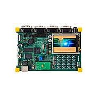
Manufacturer Part Number
IAR-KSK-IMX25
Description
KIT DEVELOPMENT I.MX257, ARM926
Manufacturer
Freescale Semiconductor
Series
i.MX25r
Type
MCUr
Datasheets
1.MCIMX25WPDKJ.pdf
(2 pages)
2.IAR-KSK-IMX25.pdf
(154 pages)
3.IAR-KSK-IMX25.pdf
(2 pages)
4.IAR-KSK-IMX25.pdf
(57 pages)
Specifications of IAR-KSK-IMX25
Contents
Board, Cables, CD, Debugger, Power Supply
Processor To Be Evaluated
I.MX257
Processor Series
i.MX25
Data Bus Width
16 bit
Interface Type
UART, JTAG, USB, Ethernet, SD/MMC
Core
ARM926EJ-S
Silicon Manufacturer
Freescale
Core Architecture
ARM
Core Sub-architecture
ARM9
Silicon Core Number
I.MX2
Silicon Family Name
I.MX25
Mcu Supported Families
I.MX25
For Use With/related Products
i.MX25
Lead Free Status / RoHS Status
Lead free / RoHS Compliant


3.7.4.2
Figure 22
(P1–P6) that are shown in the figure. In ungated mode the VSYNC and PIXCLK signals are used, and the
HSYNC signal is ignored.
54
P1
P2
P3
P4
P5
P6
P7
P1
P2
P3
P4
P5
P6
ID
ID
Figure 22. CSI Ungated Clock Mode—Sensor Data at Falling Edge, Latch Data at Rising Edge
shows the ungated clock mode timings of CSI, and
CSI VSYNC to HSYNC time
CSI HSYNC setup time
CSI DATA setup time
CSI DATA hold time
CSI pixel clock high time
CSI pixel clock low time
CSI pixel clock frequency
CSI VSYNC to pixel clock time
CSI DATA setup time
CSI DATA hold time
CSI pixel clock high time
CSI pixel clock low time
CSI pixel clock frequency
Ungated Clock Mode Timing
DATA[15:0]
VSYNC
PIXCLK
i.MX25 Applications Processor for Consumer and Industrial Products, Rev. 8
Table 42. CSI Ungated Clock Mode Timing Parameters
Parameter
Parameter
Table 41. CSI Gated Clock Mode Timing Parameters
P1
P2
P3
tVSYNC
Symbol
Symbol
tCLKh
tCLKh
tCLKl
tCLKl
tV2H
fCLK
fCLK
tHsu
tDsu
tDsu
tDh
tDh
Table 42
P4
P6
P5
Min.
Min.
67.5
67.5
describes the timing parameters
1.2
1.2
10
10
10
10
—
—
1
1
1
48
48
Freescale Semiconductor
Max.
Max.
±
±
—
—
—
—
—
—
—
—
—
—
—
10%
10%
Units
Units
MHz
MHz
ns
ns
ns
ns
ns
ns
ns
ns
ns
ns
ns
Related parts for IAR-KSK-IMX25
Image
Part Number
Description
Manufacturer
Datasheet
Request
R

Part Number:
Description:
Manufacturer:
Freescale Semiconductor, Inc
Datasheet:
Part Number:
Description:
Manufacturer:
Freescale Semiconductor, Inc
Datasheet:
Part Number:
Description:
Manufacturer:
Freescale Semiconductor, Inc
Datasheet:
Part Number:
Description:
Manufacturer:
Freescale Semiconductor, Inc
Datasheet:
Part Number:
Description:
Manufacturer:
Freescale Semiconductor, Inc
Datasheet:
Part Number:
Description:
Manufacturer:
Freescale Semiconductor, Inc
Datasheet:
Part Number:
Description:
Manufacturer:
Freescale Semiconductor, Inc
Datasheet:
Part Number:
Description:
Manufacturer:
Freescale Semiconductor, Inc
Datasheet:
Part Number:
Description:
Manufacturer:
Freescale Semiconductor, Inc
Datasheet:
Part Number:
Description:
Manufacturer:
Freescale Semiconductor, Inc
Datasheet:
Part Number:
Description:
Manufacturer:
Freescale Semiconductor, Inc
Datasheet:
Part Number:
Description:
Manufacturer:
Freescale Semiconductor, Inc
Datasheet:
Part Number:
Description:
Manufacturer:
Freescale Semiconductor, Inc
Datasheet:
Part Number:
Description:
Manufacturer:
Freescale Semiconductor, Inc
Datasheet:
Part Number:
Description:
Manufacturer:
Freescale Semiconductor, Inc
Datasheet: