IAR-KSK-IMX25 Freescale Semiconductor, IAR-KSK-IMX25 Datasheet - Page 99
IAR-KSK-IMX25
Manufacturer Part Number
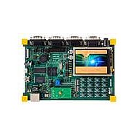
IAR-KSK-IMX25
Description
KIT DEVELOPMENT I.MX257, ARM926
Manufacturer
Freescale Semiconductor
Series
i.MX25r
Type
MCUr
Datasheets
1.MCIMX25WPDKJ.pdf
(2 pages)
2.IAR-KSK-IMX25.pdf
(154 pages)
3.IAR-KSK-IMX25.pdf
(2 pages)
4.IAR-KSK-IMX25.pdf
(57 pages)
Specifications of IAR-KSK-IMX25
Contents
Board, Cables, CD, Debugger, Power Supply
Processor To Be Evaluated
I.MX257
Processor Series
i.MX25
Data Bus Width
16 bit
Interface Type
UART, JTAG, USB, Ethernet, SD/MMC
Core
ARM926EJ-S
Silicon Manufacturer
Freescale
Core Architecture
ARM
Core Sub-architecture
ARM9
Silicon Core Number
I.MX2
Silicon Family Name
I.MX25
Mcu Supported Families
I.MX25
For Use With/related Products
i.MX25
Lead Free Status / RoHS Status
Lead free / RoHS Compliant


SIMx_DATAy_RX_TX
Table 76
3.7.14.2
Figure 71
requirements for parameters (SI7–SI10) shown in the figure.
The power-down sequence for the SIM interface is as follows:
Each of the above steps requires one CKIL period (usually 32 kHz). Power-down may be initiated by a
SIM card removal detection; or it may be launched by the processor.
Freescale Semiconductor
SIMx_SVENy
SIMx_RSTy
SIMx_CLKy
•
•
•
•
•
SIMx_SIMPDy port detects the removal of the SIM Card
SIMx_RSTy is negated
SIMx_CLKy is negated
SIMx_DATAy_RX_TX is negated
SIMx_SVENy is negated
defines the general timing requirements for the SIM interface.
Ref No.
shows the SIM interface power-down AC timing diagram.
1
2
3
SIM Power-Down Sequence
Table 76. Timing Specifications, Active-Low-Reset SIM Card Reset Sequence
T0
i.MX25 Applications Processor for Consumer and Industrial Products, Rev. 8
1
Figure 70. Active-Low-Reset SIM Card Reset Sequence
40,000
Min.
400
3
—
T1
40,000
Max.
200
—
2
Table 77
3
shows the timing
RESPONSE
clk cycles
clk cycles
clk cycles
Unit
99
Related parts for IAR-KSK-IMX25
Image
Part Number
Description
Manufacturer
Datasheet
Request
R

Part Number:
Description:
Manufacturer:
Freescale Semiconductor, Inc
Datasheet:
Part Number:
Description:
Manufacturer:
Freescale Semiconductor, Inc
Datasheet:
Part Number:
Description:
Manufacturer:
Freescale Semiconductor, Inc
Datasheet:
Part Number:
Description:
Manufacturer:
Freescale Semiconductor, Inc
Datasheet:
Part Number:
Description:
Manufacturer:
Freescale Semiconductor, Inc
Datasheet:
Part Number:
Description:
Manufacturer:
Freescale Semiconductor, Inc
Datasheet:
Part Number:
Description:
Manufacturer:
Freescale Semiconductor, Inc
Datasheet:
Part Number:
Description:
Manufacturer:
Freescale Semiconductor, Inc
Datasheet:
Part Number:
Description:
Manufacturer:
Freescale Semiconductor, Inc
Datasheet:
Part Number:
Description:
Manufacturer:
Freescale Semiconductor, Inc
Datasheet:
Part Number:
Description:
Manufacturer:
Freescale Semiconductor, Inc
Datasheet:
Part Number:
Description:
Manufacturer:
Freescale Semiconductor, Inc
Datasheet:
Part Number:
Description:
Manufacturer:
Freescale Semiconductor, Inc
Datasheet:
Part Number:
Description:
Manufacturer:
Freescale Semiconductor, Inc
Datasheet:
Part Number:
Description:
Manufacturer:
Freescale Semiconductor, Inc
Datasheet: