IAR-KSK-IMX25 Freescale Semiconductor, IAR-KSK-IMX25 Datasheet - Page 95
IAR-KSK-IMX25
Manufacturer Part Number
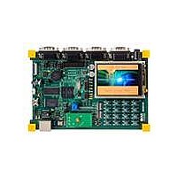
IAR-KSK-IMX25
Description
KIT DEVELOPMENT I.MX257, ARM926
Manufacturer
Freescale Semiconductor
Series
i.MX25r
Type
MCUr
Datasheets
1.MCIMX25WPDKJ.pdf
(2 pages)
2.IAR-KSK-IMX25.pdf
(154 pages)
3.IAR-KSK-IMX25.pdf
(2 pages)
4.IAR-KSK-IMX25.pdf
(57 pages)
Specifications of IAR-KSK-IMX25
Contents
Board, Cables, CD, Debugger, Power Supply
Processor To Be Evaluated
I.MX257
Processor Series
i.MX25
Data Bus Width
16 bit
Interface Type
UART, JTAG, USB, Ethernet, SD/MMC
Core
ARM926EJ-S
Silicon Manufacturer
Freescale
Core Architecture
ARM
Core Sub-architecture
ARM9
Silicon Core Number
I.MX2
Silicon Family Name
I.MX25
Mcu Supported Families
I.MX25
For Use With/related Products
i.MX25
Lead Free Status / RoHS Status
Lead free / RoHS Compliant


1
3.7.13
Figure 67
The PWM can be programmed to select one of three clock signals as its source frequency. The selected
clock signal is passed through a prescaler before being input to the counter. The output is available at the
pulse width modulator output (PWMO) external pin.
Freescale Semiconductor
T is pixel clock period
VSYNC
HSYNC
HSYNC
LSCLK
T1
T2
T3
T4
T5
T6
ID
OE
LD
depicts the timing of the PWM, and
Pixel clock period
HSYNC width
LD setup time
LD hold time
Delay from the end of HSYNC to the beginning of the OE pulse
Delay from end of OE to the beginning of the HSYNC pulse
Pulse Width Modulator (PWM) Timing Parameters
T2
Line 1
i.MX25 Applications Processor for Consumer and Industrial Products, Rev. 8
T5
Line 2
T3
T1
Table 72. LCDC TFT Mode Timing Parameters
Figure 66. LCDC TFT Mode Timing Diagram
T4
Description
Table 73
lists the PWM timing characteristics.
Line n
Min.
22.5
1
5
5
3
1
Line 1
1000
Ma
—
—
—
—
—
T6
Unit
ns
T
ns
ns
T
T
1
1
1
95
Related parts for IAR-KSK-IMX25
Image
Part Number
Description
Manufacturer
Datasheet
Request
R

Part Number:
Description:
Manufacturer:
Freescale Semiconductor, Inc
Datasheet:
Part Number:
Description:
Manufacturer:
Freescale Semiconductor, Inc
Datasheet:
Part Number:
Description:
Manufacturer:
Freescale Semiconductor, Inc
Datasheet:
Part Number:
Description:
Manufacturer:
Freescale Semiconductor, Inc
Datasheet:
Part Number:
Description:
Manufacturer:
Freescale Semiconductor, Inc
Datasheet:
Part Number:
Description:
Manufacturer:
Freescale Semiconductor, Inc
Datasheet:
Part Number:
Description:
Manufacturer:
Freescale Semiconductor, Inc
Datasheet:
Part Number:
Description:
Manufacturer:
Freescale Semiconductor, Inc
Datasheet:
Part Number:
Description:
Manufacturer:
Freescale Semiconductor, Inc
Datasheet:
Part Number:
Description:
Manufacturer:
Freescale Semiconductor, Inc
Datasheet:
Part Number:
Description:
Manufacturer:
Freescale Semiconductor, Inc
Datasheet:
Part Number:
Description:
Manufacturer:
Freescale Semiconductor, Inc
Datasheet:
Part Number:
Description:
Manufacturer:
Freescale Semiconductor, Inc
Datasheet:
Part Number:
Description:
Manufacturer:
Freescale Semiconductor, Inc
Datasheet:
Part Number:
Description:
Manufacturer:
Freescale Semiconductor, Inc
Datasheet: