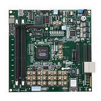
LFE3-95E-PCIE-DKN Lattice, LFE3-95E-PCIE-DKN Datasheet - Page 69

LFE3-95E-PCIE-DKN
Manufacturer Part Number
LFE3-95E-PCIE-DKN
Description
MCU, MPU & DSP Development Tools LatticeECP3 PCI Express Dev Kit
Manufacturer
Lattice
Datasheet
1.LFE3-150EA-7FN672CTW.pdf
(130 pages)
Specifications of LFE3-95E-PCIE-DKN
Processor To Be Evaluated
LFE3-95EA-x
Processor Series
LatticeECP3
Interface Type
SPI
Operating Supply Voltage
1.2 V to 3.3 V
Lead Free Status / RoHS Status
Lead free / RoHS Compliant
- Current page: 69 of 130
- Download datasheet (3Mb)
LatticeECP3 External Switching Characteristics (Continued)
Lattice Semiconductor
f
General I/O Pin Parameters Using Dedicated Clock Input Primary Clock with PLL with Clock Injection Removal Setting
t
t
t
t
t
t
t
t
t
t
Generic DDR
Generic DDRX1 Inputs with Clock and Data (>10 Bits Wide) Centered at Pin (GDDRX1_RX.SCLK.Centered) Using PCLK
Pin for Clock Input
Data Left, Right and Top Sides & Clock Left, Right and Top Sides
t
t
f
Generic DDRX1 Inputs with Clock in the Center of Data Window, without DLL (GDDRX1_RX.ECLK.Centered)
t
t
f
Generic DDRX1 Inputs with Clock and Data (> 10 Bits Wide) Aligned at Pin (GDDRX1_RX.SCLK.Aligned) using DLL-
CLKIN Pin for Clock Input
Data Left, Right and Top Sides & Clock Left and Right Sides
t
t
f
Generic DDRX1 Inputs with Clock and Data Aligned, with DLL (GDDRX1_RX.ECLK.Aligned)
t
t
MAX_IO
COPLL
SUPLL
HPLL
SU_DELPLL
H_DELPLL
COPLL
SUPLL
HPLL
SU_DELPLL
H_DELPLL
SUGDDR
HGDDR
MAX_GDDR
SUGDDR
HOGDDR
MAX_GDDR
DVACLKGDDR
DVECLKGDDR
MAX_GDDR
DVACLKGDDR
DVECLKGDDR
Parameter
Parameter
Clock Frequency of I/O and PFU Reg-
ister
Clock to Output - PIO Output Register ECP3-150EA
Clock to Data Setup - PIO Input Regis-
ter
Clock to Data Hold - PIO Input Regis-
ter
Clock to Data Setup - PIO Input Regis-
ter with Data Input Delay
Clock to Data Hold - PIO Input Regis-
ter with Input Data Delay
Clock to Output - PIO Output Register ECP3-70E/95E
Clock to Data Setup - PIO Input Regis-
ter
Clock to Data Hold - PIO Input Regis-
ter
Clock to Data Setup - PIO Input Regis-
ter with Data Input Delay
Clock to Data Hold - PIO Input Regis-
ter with Input Data Delay
Data Setup Before CLK
Data Hold After CLK
DDRX1 Clock Frequency
Data Setup Before CLK
Data Hold After CLK
DDRX1 Clock Frequency
Data Setup Before CLK
Data Hold After CLK
DDRX1 Clock Frequency
Data Setup Before CLK
Data Hold After CLK
Over Recommended Commercial Operating Conditions
Description
Description
ECP3-70E/95E
ECP3-150EA
ECP3-150EA
ECP3-150EA
ECP3-150EA
ECP3-70E/95E
ECP3-70E/95E
ECP3-70E/95E
ECP3-70E/95E
ECP3-150EA
ECP3-150EA
ECP3-150EA
ECP3-70E/95E
ECP3-70E/95E
ECP3-70E/95E
ECP3-150EA
ECP3-150EA
ECP3-150EA
ECP3-70E/95E
ECP3-70E/95E 0.765
3-17
Device
Device
Min.
Min.
515
515
0.6
0.9
1.5
0.6
0.9
1.6
0.0
—
—
—
—
—
—
—
—
—
DC and Switching Characteristics
-8
-8
LatticeECP3 Family Data Sheet
0.235
Max.
Max.
500
250
2.5
0.1
2.2
—
—
—
—
—
—
—
—
—
—
—
—
—
0.765
Min.
Min.
515
515
0.6
1.0
1.6
0.7
1.1
1.9
0.0
—
—
—
—
—
—
—
—
—
-7
-7
0.235
Max.
Max.
420
250
2.7
0.1
2.3
1, 2
—
—
—
—
—
—
—
—
—
—
—
—
—
0.765
Min.
Min.
515
515
0.7
1.1
1.8
0.8
1.3
2.1
0.0
—
—
—
—
—
—
—
—
—
-6
-6
0.235
Max.
Max.
375
250
3.1
0.1
2.5
—
—
—
—
—
—
—
—
—
—
—
—
—
Units
Units
MHz
MHz
MHz
Mhz
ns
ns
ns
ns
ns
ns
ns
ns
ns
ns
ps
ps
ps
ps
UI
UI
UI
UI
2
Related parts for LFE3-95E-PCIE-DKN
Image
Part Number
Description
Manufacturer
Datasheet
Request
R

Part Number:
Description:
FPGA - Field Programmable Gate Array 92K LUTs, 490 I/O 8 Speed
Manufacturer:
Lattice

Part Number:
Description:
FPGA - Field Programmable Gate Array 92K LUTs, 380 I/O 7 Speed
Manufacturer:
Lattice

Part Number:
Description:
FPGA - Field Programmable Gate Array 92K LUTs, 295 I/O 7 Speed
Manufacturer:
Lattice

Part Number:
Description:
FPGA - Field Programmable Gate Array 92K LUTs, 380 I/O 6 Speed
Manufacturer:
Lattice

Part Number:
Description:
FPGA - Field Programmable Gate Array 92K LUTs, 490 I/O 6 Speed
Manufacturer:
Lattice

Part Number:
Description:
FPGA - Field Programmable Gate Array 92K LUTs, 295 I/O 8 Speed
Manufacturer:
Lattice

Part Number:
Description:
FPGA - Field Programmable Gate Array 92K LUTs, 490 I/O 8 Speed
Manufacturer:
Lattice

Part Number:
Description:
FPGA - Field Programmable Gate Array 92K LUTs, 380 I/O 8 Speed
Manufacturer:
Lattice

Part Number:
Description:
FPGA - Field Programmable Gate Array 92K LUTs, 490 I/O 6 Speed
Manufacturer:
Lattice

Part Number:
Description:
FPGA - Field Programmable Gate Array 92K LUTs, 295 I/O 6 Speed
Manufacturer:
Lattice

Part Number:
Description:
FPGA - Field Programmable Gate Array 92K LUTs, 490 I/O 7 Speed
Manufacturer:
Lattice

Part Number:
Description:
FPGA - Field Programmable Gate Array 92K LUTs, 295 I/O 8 Speed
Manufacturer:
Lattice

Part Number:
Description:
FPGA - Field Programmable Gate Array 92K LUTs, 490 I/O 7 Speed
Manufacturer:
Lattice

Part Number:
Description:
FPGA - Field Programmable Gate Array 92K LUTs, 380 I/O 6 Speed
Manufacturer:
Lattice

Part Number:
Description:
FPGA - Field Programmable Gate Array 92K LUTs, 295 I/O 7 Speed
Manufacturer:
Lattice


