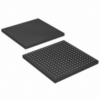
XC3S250E-4FTG256C Xilinx Inc, XC3S250E-4FTG256C Datasheet - Page 55

XC3S250E-4FTG256C
Manufacturer Part Number
XC3S250E-4FTG256C
Description
IC SPARTAN-3E FPGA 250K 256-FTBG
Manufacturer
Xilinx Inc
Series
Spartan™-3Er
Datasheet
1.XC3S100E-4VQG100C.pdf
(233 pages)
Specifications of XC3S250E-4FTG256C
Total Ram Bits
221184
Number Of Logic Elements/cells
5508
Number Of Labs/clbs
612
Number Of I /o
172
Number Of Gates
250000
Voltage - Supply
1.14 V ~ 1.26 V
Mounting Type
Surface Mount
Operating Temperature
0°C ~ 85°C
Package / Case
256-LBGA
No. Of Logic Blocks
5508
No. Of Gates
250000
No. Of Macrocells
5508
No. Of Speed Grades
4
No. Of I/o's
190
Clock Management
DLL
Lead Free Status / RoHS Status
Lead free / RoHS Compliant
Other names
122-1482
Available stocks
Company
Part Number
Manufacturer
Quantity
Price
Company:
Part Number:
XC3S250E-4FTG256C
Manufacturer:
TOS
Quantity:
3 012
Company:
Part Number:
XC3S250E-4FTG256C
Manufacturer:
XILINX
Quantity:
281
Part Number:
XC3S250E-4FTG256C
Manufacturer:
ALTERA/阿尔特拉
Quantity:
20 000
The CLKFX_DIVIDE is an integer ranging from 1 to 32,
inclusive and forms the denominator in
example, if CLKFX_MULTIPLY = 5 and CLKFX_DIVIDE = 3,
the frequency of the output clock signal is 5/3 that of the
input clock signal. These attributes and their acceptable
ranges are described in
Table 34: DFS Attributes
Any combination of integer values can be assigned to the
CLKFX_MULTIPLY and CLKFX_DIVIDE attributes, pro-
vided that two conditions are met:
1. The two values fall within their corresponding ranges,
2. The f
DFS With or Without the DLL
Although the CLKIN input is shared with both units, the DFS
unit functions with or separately from the DLL unit. Separate
from the DLL, the DFS generates an output frequency from
the
CLKFX_MULTIPLY and CLKFX_DIVIDE values. Frequency
synthesis does not require a feedback loop. Furthermore,
without the DLL, the DFS unit supports a broader operating
frequency range.
With the DLL, the DFS unit operates as described above,
only with the additional benefit of eliminating the clock distri-
bution delay. In this case, a feedback loop from the CLK0 or
CLK2X output to the CLKFB input must be present.
When operating with the DLL unit, the DFS’s CLKFX and
CLKFX180 outputs are phase-aligned with the CLKIN input
every CLKFX_DIVIDE cycles of CLKIN and every
CLKFX_MULTIPLY cycles of CLKFX. For example, when
CLKFX_MULTIPLY = 5 and CLKFX_DIVIDE = 3, the input
Table 35: PS Attributes
DS312-2 (v3.8) August 26, 2009
Product Specification
CLKFX_MULTIPLY
CLKFX_DIVIDE
CLKOUT_PHASE_SHIFT
PHASE_SHIFT
as specified in
falls within the DCM’s operating frequency
specifications (see
CLKIN
Attribute
CLKFX
Attribute
R
frequency
output frequency calculated in
Table
Table 107
Frequency
multiplier
constant
Frequency divisor
constant
Table
34.
Description
according
34.
in Module 3).
Disables the PS component or chooses between
Fixed Phase and Variable Phase modes.
Determines size and direction of initial fine phase
shift.
to
Equation
the
Integer from
2 to 32,
inclusive
Integer from
1 to 32,
inclusive
Equation 1
Values
respective
1. For
Description
www.xilinx.com
and output clock edges coincide every three CLKIN input
periods, which is equivalent in time to five CLKFX output
periods.
Smaller CLKFX_MULTIPLY and CLKFX_DIVIDE values
result in faster lock times. Therefore, CLKFX_MULTIPLY
and CLKFX_DIVIDE must be factored to reduce their values
wherever possible. For example, given CLKFX_MULTIPLY
= 9 and CLKFX_DIVIDE = 6, removing a factor of three
yields CLKFX_MULTIPLY = 3 and CLKFX_DIVIDE = 2.
While both value-pairs result in the multiplication of clock
frequency by 3/2, the latter value-pair enables the DLL to
lock more quickly.
Phase Shifter (PS)
The DCM provides two approaches to controlling the phase
of a DCM clock output signal relative to the CLKIN signal:
First, eight of the nine DCM clock outputs
CLK180, CLK270, CLK2X, CLK2X180, CLKFX, and
CLKFX180
shifting of the input clock.
Second, the PS unit provides additional fine phase shift
control of all nine DCM outputs. The PS unit accomplishes
this by introducing a “fine phase shift” delay (T
the CLKFB and CLKIN signals inside the DLL unit. In FIXED
phase shift mode, the fine phase shift is specified at design
time with a resolution down to
one delay step (DCM_DELAY_STEP), whichever is greater.
This fine phase shift value is relative to the coarser quadrant
or half-period phase shift of the DCM clock output. When
used, the PS unit shifts the phase of all nine DCM clock out-
put signals.
Enabling Phase Shifting and Selecting an Operat-
ing Mode
The CLKOUT_PHASE_SHIFT attribute controls the PS unit
for the specific DCM instantiation. As described in
this attribute has three possible values: NONE, FIXED, and
VARIABLE. When CLKOUT_PHASE_SHIFT = NONE, the
PS unit is disabled and the DCM output clocks are
phase-aligned to the CLKIN input via the CLKFB feedback
path.
The PS unit is enabled when the CLKOUT_PHASE_SHIFT
attribute is set to FIXED or VARIABLE modes. These two
modes are described in the sections that follow.
Figure 44a
–
provide either quadrant or half-period phase
shows this case.
NONE, FIXED, VARIABLE
Integers from –255 to +255
1
/
256
Functional Description
th
Values
of a CLKIN cycle or
–
CLK0, CLK90,
PS
) between
Table
35,
55


