MC68SEC000AA16 Freescale Semiconductor, MC68SEC000AA16 Datasheet - Page 201
MC68SEC000AA16
Manufacturer Part Number
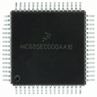
MC68SEC000AA16
Description
IC MPU 32BIT 16MHZ 64-QFP
Manufacturer
Freescale Semiconductor
Series
M68000r
Specifications of MC68SEC000AA16
Processor Type
M680x0 32-Bit
Speed
16MHz
Voltage
3.3V, 5V
Mounting Type
Surface Mount
Package / Case
64-QFP
Processor Series
M680xx
Core
CPU32
Maximum Clock Frequency
16 MHz
Operating Supply Voltage
3.3 V, 5 V
Maximum Operating Temperature
+ 105 C
Mounting Style
SMD/SMT
Minimum Operating Temperature
0 C
Core Size
32 Bit
Cpu Speed
16MHz
Digital Ic Case Style
QFP
No. Of Pins
64
Supply Voltage Range
5V
Operating Temperature Range
0°C To +70°C
Frequency Typ
20MHz
Filter Terminals
SMD
Rohs Compliant
Yes
Clock Frequency
16MHz
Lead Free Status / RoHS Status
Lead free / RoHS Compliant
Features
-
Lead Free Status / Rohs Status
Lead free / RoHS Compliant
Available stocks
Company
Part Number
Manufacturer
Quantity
Price
Company:

Part Number:
MC68SEC000AA16
Manufacturer:
Freescale Semiconductor
Quantity:
10 000
Part Number:
MC68SEC000AA16
Manufacturer:
FREESCALE
Quantity:
20 000
Company:
Part Number:
MC68SEC000AA16R2
Manufacturer:
Freescale Semiconductor
Quantity:
10 000


UPLOAD Utility
UPLOAD Utility
The UPLOAD utility subroutine transfers data from the MCU to a host computer system over the SCI serial
data link.
NOTE
Only EPROM versions of the M68HC11 include this utility.
Verification of EPROM contents is one example of how the UPLOAD utility could be used. Before calling
this program, the Y index register is loaded (by user firmware) with the address of the first data byte to be
uploaded. If a baud rate other than the current SCI baud rate is to be used for the upload process, the
user’s firmware must also write to the baud register. The UPLOAD program sends successive bytes of
data out the SCI transmitter until a reset is issued (the upload loop is infinite).
For a complete commented listing example of the UPLOAD utility, refer to
Listing 3. MC68HC711E9
Bootloader
ROM.
EPROM Programming Utility
The EPROM programming utility is one way of programming data into the internal EPROM of the
MC68HC711E9 MCU. An external 12-V programming power supply is required to program on-chip
EPROM. The simplest way to use this utility program is to bootload a 3-byte program consisting of a single
jump instruction to the start of the PROGRAM utility program ($BF00). The bootloader program sets the
X and Y index registers to default values before jumping to the downloaded program (see [16] at the
bottom of
Figure
3). When the host computer sees the $FF character, data to be programmed into the
EPROM is sent, starting with the character for location $D000. After the last byte to be programmed is
sent to the MC68HC711E9 and the corresponding verification data is returned to the host, the
programming operation is terminated by resetting the MCU.
The number of bytes to be programmed, the first address to be programmed, and the programming time
can be controlled by the user if values other than the default values are desired.
To understand the detailed operation of the EPROM programming utility, refer to
Figure 4
during the
following discussion.
Figure 4
is composed of three interrelated parts. The upper-left portion shows the
flowchart of the PROGRAM utility running in the boot ROM of the MCU. The upper-right portion shows
the flowchart for the user-supplied driver program running in the host computer. The lower portion of
Figure 4
is a timing sequence showing the relationship of operations between the MCU and the host
computer. Reference numbers in the flowcharts in the upper half of
Figure 4
have matching numbers in
the lower half to help the reader relate the three parts of the figure.
The shaded area [1] refers to the software and hardware latency in the MCU leading to the transmission
of a character (in this case, the $FF). The shaded area [2] refers to a similar latency in the host computer
(in this case, leading to the transmission of the first data character to the MCU).
The overall operation begins when the MCU sends the first character ($FF) to the host computer,
indicating that it is ready for the first data character. The host computer sends the first data byte [3] and
enters its main loop. The second data character is sent [4], and the host then waits [5] for the first verify
byte to come back from the MCU.
M68HC11 Bootstrap Mode, Rev. 1.1
Freescale Semiconductor
201
Related parts for MC68SEC000AA16
Image
Part Number
Description
Manufacturer
Datasheet
Request
R

Part Number:
Description:
Manufacturer:
Freescale Semiconductor, Inc
Datasheet:
Part Number:
Description:
Manufacturer:
Freescale Semiconductor, Inc
Datasheet:
Part Number:
Description:
Manufacturer:
Freescale Semiconductor, Inc
Datasheet:
Part Number:
Description:
Manufacturer:
Freescale Semiconductor, Inc
Datasheet:
Part Number:
Description:
Manufacturer:
Freescale Semiconductor, Inc
Datasheet:
Part Number:
Description:
Manufacturer:
Freescale Semiconductor, Inc
Datasheet:
Part Number:
Description:
Manufacturer:
Freescale Semiconductor, Inc
Datasheet:
Part Number:
Description:
Manufacturer:
Freescale Semiconductor, Inc
Datasheet:
Part Number:
Description:
Manufacturer:
Freescale Semiconductor, Inc
Datasheet:
Part Number:
Description:
Manufacturer:
Freescale Semiconductor, Inc
Datasheet:
Part Number:
Description:
Manufacturer:
Freescale Semiconductor, Inc
Datasheet:
Part Number:
Description:
Manufacturer:
Freescale Semiconductor, Inc
Datasheet:
Part Number:
Description:
Manufacturer:
Freescale Semiconductor, Inc
Datasheet:
Part Number:
Description:
Manufacturer:
Freescale Semiconductor, Inc
Datasheet:
Part Number:
Description:
Manufacturer:
Freescale Semiconductor, Inc
Datasheet: