MC68SEC000AA16 Freescale Semiconductor, MC68SEC000AA16 Datasheet - Page 82
MC68SEC000AA16
Manufacturer Part Number
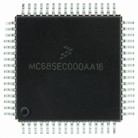
MC68SEC000AA16
Description
IC MPU 32BIT 16MHZ 64-QFP
Manufacturer
Freescale Semiconductor
Series
M68000r
Specifications of MC68SEC000AA16
Processor Type
M680x0 32-Bit
Speed
16MHz
Voltage
3.3V, 5V
Mounting Type
Surface Mount
Package / Case
64-QFP
Processor Series
M680xx
Core
CPU32
Maximum Clock Frequency
16 MHz
Operating Supply Voltage
3.3 V, 5 V
Maximum Operating Temperature
+ 105 C
Mounting Style
SMD/SMT
Minimum Operating Temperature
0 C
Core Size
32 Bit
Cpu Speed
16MHz
Digital Ic Case Style
QFP
No. Of Pins
64
Supply Voltage Range
5V
Operating Temperature Range
0°C To +70°C
Frequency Typ
20MHz
Filter Terminals
SMD
Rohs Compliant
Yes
Clock Frequency
16MHz
Lead Free Status / RoHS Status
Lead free / RoHS Compliant
Features
-
Lead Free Status / Rohs Status
Lead free / RoHS Compliant
Available stocks
Company
Part Number
Manufacturer
Quantity
Price
Company:

Part Number:
MC68SEC000AA16
Manufacturer:
Freescale Semiconductor
Quantity:
10 000
Part Number:
MC68SEC000AA16
Manufacturer:
FREESCALE
Quantity:
20 000
Company:
Part Number:
MC68SEC000AA16R2
Manufacturer:
Freescale Semiconductor
Quantity:
10 000


Resets and Interrupts
5.2.5 System Configuration Options Register
ADPU — Analog-to-Digital Converter Power-Up Bit
CSEL — Clock Select Bit
IRQE — Configure IRQ for Edge-Sensitive-Only Operation Bit
DLY — Enable Oscillator Startup Delay Bit
CME — Clock Monitor Enable Bit
Bit 2 — Unimplemented
CR[1:0] — COP Timer Rate Select Bit
82
Refer to
Refer to
Refer to
Converter.
This control bit can be read or written at any time and controls whether or not the internal clock monitor
circuit triggers a reset sequence when the system clock is slow or absent. When it is clear, the clock
monitor circuit is disabled, and when it is set, the clock monitor circuit is enabled. Reset clears the CME
bit.
Always reads 0
The internal E clock is first divided by 2
bits determine a scaling factor for the watchdog timer. See
0 = IRQ is configured for level-sensitive operation.
1 = IRQ is configured for edge-sensitive-only operation.
0 = Clock monitor circuit disabled
1 = Slow or stopped clocks cause reset
Chapter 3 Analog-to-Digital (A/D)
Chapter 3 Analog-to-Digital (A/D)
Chapter 2 Operating Modes and On-Chip Memory
1. Can be written only once in first 64 cycles out of reset in normal mode or at any time in special modes
Address:
Reset:
Read:
Write:
Figure 5-2. System Configuration Options Register (OPTION)
$1039
ADPU
Bit 7
0
= Unimplemented
CSEL
0
6
M68HC11E Family Data Sheet, Rev. 5.1
IRQE
15
5
0
(1)
before it enters the COP watchdog system. These control
Converter.
Converter.
DLY
4
1
(1)
CME
3
0
Table 5-1
and
Chapter 3 Analog-to-Digital (A/D)
2
0
for specific timeout settings.
CR1
1
0
(1)
Freescale Semiconductor
CR0
Bit 0
0
(1)
Related parts for MC68SEC000AA16
Image
Part Number
Description
Manufacturer
Datasheet
Request
R

Part Number:
Description:
Manufacturer:
Freescale Semiconductor, Inc
Datasheet:
Part Number:
Description:
Manufacturer:
Freescale Semiconductor, Inc
Datasheet:
Part Number:
Description:
Manufacturer:
Freescale Semiconductor, Inc
Datasheet:
Part Number:
Description:
Manufacturer:
Freescale Semiconductor, Inc
Datasheet:
Part Number:
Description:
Manufacturer:
Freescale Semiconductor, Inc
Datasheet:
Part Number:
Description:
Manufacturer:
Freescale Semiconductor, Inc
Datasheet:
Part Number:
Description:
Manufacturer:
Freescale Semiconductor, Inc
Datasheet:
Part Number:
Description:
Manufacturer:
Freescale Semiconductor, Inc
Datasheet:
Part Number:
Description:
Manufacturer:
Freescale Semiconductor, Inc
Datasheet:
Part Number:
Description:
Manufacturer:
Freescale Semiconductor, Inc
Datasheet:
Part Number:
Description:
Manufacturer:
Freescale Semiconductor, Inc
Datasheet:
Part Number:
Description:
Manufacturer:
Freescale Semiconductor, Inc
Datasheet:
Part Number:
Description:
Manufacturer:
Freescale Semiconductor, Inc
Datasheet:
Part Number:
Description:
Manufacturer:
Freescale Semiconductor, Inc
Datasheet:
Part Number:
Description:
Manufacturer:
Freescale Semiconductor, Inc
Datasheet: