MC68SEC000AA16 Freescale Semiconductor, MC68SEC000AA16 Datasheet - Page 204
MC68SEC000AA16
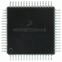
Manufacturer Part Number
MC68SEC000AA16
Description
IC MPU 32BIT 16MHZ 64-QFP
Manufacturer
Freescale Semiconductor
Series
M68000r
Specifications of MC68SEC000AA16
Processor Type
M680x0 32-Bit
Speed
16MHz
Voltage
3.3V, 5V
Mounting Type
Surface Mount
Package / Case
64-QFP
Processor Series
M680xx
Core
CPU32
Maximum Clock Frequency
16 MHz
Operating Supply Voltage
3.3 V, 5 V
Maximum Operating Temperature
+ 105 C
Mounting Style
SMD/SMT
Minimum Operating Temperature
0 C
Core Size
32 Bit
Cpu Speed
16MHz
Digital Ic Case Style
QFP
No. Of Pins
64
Supply Voltage Range
5V
Operating Temperature Range
0°C To +70°C
Frequency Typ
20MHz
Filter Terminals
SMD
Rohs Compliant
Yes
Clock Frequency
16MHz
Lead Free Status / RoHS Status
Lead free / RoHS Compliant
Features
-
Lead Free Status / Rohs Status
Lead free / RoHS Compliant
Available stocks
Company
Part Number
Manufacturer
Quantity
Price
Company:

Part Number:
MC68SEC000AA16
Manufacturer:
Freescale Semiconductor
Quantity:
10 000
Part Number:
MC68SEC000AA16
Manufacturer:
FREESCALE
Quantity:
20 000
Company:
Part Number:
MC68SEC000AA16R2
Manufacturer:
Freescale Semiconductor
Quantity:
10 000


Allowing for Bootstrap Mode
In systems where the PD0/RxD pin is normally used as a general-purpose output, a serial signal from the
host can be connected to the pin without resulting in output driver conflicts. It may be important to consider
what the existing logic will do with the SCI serial data instead of the signals that would have been
produced by the PD0 pin. In systems where the PD0 pin is used normally as a general-purpose input, the
driver circuit that drives the PD0 pin must be designed so that the serial data can override this driver, or
the driver must be disconnected during the bootstrap download. A simple series resistor between the
driver and the PD0 pin solves this problem as shown in
can then be connected to the PD0/RxD pin, and the series resistor will prevent direct conflict between the
host driver and the normal PD0 driver.
TxD Pin
The bootloader program uses the PD1/TxD pin to send verification data back to the host computer. To
minimize the possibility of conflicts with circuitry connected to this pin, port D is configured for wire-OR
mode by the bootloader program during initialization. Since the wire-OR configuration prevents the pin
from driving active high levels, a pullup resistor to V
In systems where the PD1/TxD pin is normally used as a general-purpose output, there are no output
driver conflicts. It may be important to consider what the existing logic will do with the SCI serial data
instead of the signals that would have been produced by the PD1 pin.
In systems where the PD1 pin is normally used as a general-purpose input, the driver circuit that drives
the PD1 pin must be designed so that the PD1/TxD pin driver in the MCU can override this driver. A simple
series resistor between the driver and the PD1 pin can solve this problem. The TxD pin can then be
configured as an output, and the series resistor will prevent direct conflict between the internal TxD driver
and the external driver connected to PD1 through the series resistor.
Other
The bootloader firmware sets the DWOM control bit, which configures all port D pins for wire-OR
operation. During the bootloading process, all port D pins except the PD1/TxD pin are configured as
high-impedance inputs. Any port D pin that normally is used as an output should have a pullup resistor so
it does not float during the bootloading process.
204
CONTROL
EXISTING
SYSTEM
SIGNAL
FROM
Figure 5. Preventing Driver Conflict
HOST
M68HC11 Bootstrap Mode, Rev. 1.1
EXISTING
SHIFTER
DRIVER
RS232
LEVEL
CONNECTED ONLY DURING
BOOTLOADING
RESISTOR
DD
SERIES
is needed if the TxD signal is used.
Figure
5. The serial data from the host computer
RxD/PD0
(BEING USED
AS INPUT)
MC68HC11
Freescale Semiconductor
Related parts for MC68SEC000AA16
Image
Part Number
Description
Manufacturer
Datasheet
Request
R

Part Number:
Description:
Manufacturer:
Freescale Semiconductor, Inc
Datasheet:
Part Number:
Description:
Manufacturer:
Freescale Semiconductor, Inc
Datasheet:
Part Number:
Description:
Manufacturer:
Freescale Semiconductor, Inc
Datasheet:
Part Number:
Description:
Manufacturer:
Freescale Semiconductor, Inc
Datasheet:
Part Number:
Description:
Manufacturer:
Freescale Semiconductor, Inc
Datasheet:
Part Number:
Description:
Manufacturer:
Freescale Semiconductor, Inc
Datasheet:
Part Number:
Description:
Manufacturer:
Freescale Semiconductor, Inc
Datasheet:
Part Number:
Description:
Manufacturer:
Freescale Semiconductor, Inc
Datasheet:
Part Number:
Description:
Manufacturer:
Freescale Semiconductor, Inc
Datasheet:
Part Number:
Description:
Manufacturer:
Freescale Semiconductor, Inc
Datasheet:
Part Number:
Description:
Manufacturer:
Freescale Semiconductor, Inc
Datasheet:
Part Number:
Description:
Manufacturer:
Freescale Semiconductor, Inc
Datasheet:
Part Number:
Description:
Manufacturer:
Freescale Semiconductor, Inc
Datasheet:
Part Number:
Description:
Manufacturer:
Freescale Semiconductor, Inc
Datasheet:
Part Number:
Description:
Manufacturer:
Freescale Semiconductor, Inc
Datasheet: