MC68SEC000AA16 Freescale Semiconductor, MC68SEC000AA16 Datasheet - Page 57
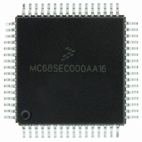
MC68SEC000AA16
Manufacturer Part Number
MC68SEC000AA16
Description
IC MPU 32BIT 16MHZ 64-QFP
Manufacturer
Freescale Semiconductor
Series
M68000r
Specifications of MC68SEC000AA16
Processor Type
M680x0 32-Bit
Speed
16MHz
Voltage
3.3V, 5V
Mounting Type
Surface Mount
Package / Case
64-QFP
Processor Series
M680xx
Core
CPU32
Maximum Clock Frequency
16 MHz
Operating Supply Voltage
3.3 V, 5 V
Maximum Operating Temperature
+ 105 C
Mounting Style
SMD/SMT
Minimum Operating Temperature
0 C
Core Size
32 Bit
Cpu Speed
16MHz
Digital Ic Case Style
QFP
No. Of Pins
64
Supply Voltage Range
5V
Operating Temperature Range
0°C To +70°C
Frequency Typ
20MHz
Filter Terminals
SMD
Rohs Compliant
Yes
Clock Frequency
16MHz
Lead Free Status / RoHS Status
Lead free / RoHS Compliant
Features
-
Lead Free Status / Rohs Status
Lead free / RoHS Compliant
Available stocks
Company
Part Number
Manufacturer
Quantity
Price
Company:

Part Number:
MC68SEC000AA16
Manufacturer:
Freescale Semiconductor
Quantity:
10 000
Part Number:
MC68SEC000AA16
Manufacturer:
FREESCALE
Quantity:
20 000
Company:
Part Number:
MC68SEC000AA16R2
Manufacturer:
Freescale Semiconductor
Quantity:
10 000


Chapter 3
Analog-to-Digital (A/D) Converter
3.1 Introduction
The analog-to-digital (A/D) system, a successive approximation converter, uses an all-capacitive charge
redistribution technique to convert analog signals to digital values.
3.2 Overview
The A/D system is an 8-channel, 8-bit, multiplexed-input converter. The converter does not require
external sample and hold circuits because of the type of charge redistribution technique used. A/D
converter timing can be synchronized to the system E clock or to an internal resistor capacitor (RC)
oscillator.
The A/D converter system consists of four functional blocks: multiplexer, analog converter, digital control,
and result storage. Refer to
Figure
3-1.
3.2.1 Multiplexer
The multiplexer selects one of 16 inputs for conversion. Input selection is controlled by the value of bits
CD:CA in the ADCTL register. The eight port E pins are fixed-direction analog inputs to the multiplexer,
and additional internal analog signal lines are routed to it.
Port E pins also can be used as digital inputs. Digital reads of port E pins are not recommended during
the sample portion of an A/D conversion cycle, when the gate signal to the N-channel input gate is on.
Because no P-channel devices are directly connected to either input pins or reference voltage pins,
voltages above V
do not cause a latchup problem, although current should be limited according to
DD
maximum ratings. Refer to
Figure
3-2, which is a functional diagram of an input pin.
3.2.2 Analog Converter
Conversion of an analog input selected by the multiplexer occurs in this block. It contains a
digital-to-analog capacitor (DAC) array, a comparator, and a successive approximation register (SAR).
Each conversion is a sequence of eight comparison operations, beginning with the most significant bit
(MSB). Each comparison determines the value of a bit in the successive approximation register.
The DAC array performs two functions. It acts as a sample and hold circuit during the entire conversion
sequence and provides comparison voltage to the comparator during each successive comparison.
The result of each successive comparison is stored in the SAR. When a conversion sequence is
complete, the contents of the SAR are transferred to the appropriate result register.
A charge pump provides switching voltage to the gates of analog switches in the multiplexer. Charge
pump output must stabilize between 7 and 8 volts within up to 100 µs before the converter can be used.
The charge pump is enabled by the ADPU bit in the OPTION register.
M68HC11E Family Data Sheet, Rev. 5.1
Freescale Semiconductor
57
Related parts for MC68SEC000AA16
Image
Part Number
Description
Manufacturer
Datasheet
Request
R

Part Number:
Description:
Manufacturer:
Freescale Semiconductor, Inc
Datasheet:
Part Number:
Description:
Manufacturer:
Freescale Semiconductor, Inc
Datasheet:
Part Number:
Description:
Manufacturer:
Freescale Semiconductor, Inc
Datasheet:
Part Number:
Description:
Manufacturer:
Freescale Semiconductor, Inc
Datasheet:
Part Number:
Description:
Manufacturer:
Freescale Semiconductor, Inc
Datasheet:
Part Number:
Description:
Manufacturer:
Freescale Semiconductor, Inc
Datasheet:
Part Number:
Description:
Manufacturer:
Freescale Semiconductor, Inc
Datasheet:
Part Number:
Description:
Manufacturer:
Freescale Semiconductor, Inc
Datasheet:
Part Number:
Description:
Manufacturer:
Freescale Semiconductor, Inc
Datasheet:
Part Number:
Description:
Manufacturer:
Freescale Semiconductor, Inc
Datasheet:
Part Number:
Description:
Manufacturer:
Freescale Semiconductor, Inc
Datasheet:
Part Number:
Description:
Manufacturer:
Freescale Semiconductor, Inc
Datasheet:
Part Number:
Description:
Manufacturer:
Freescale Semiconductor, Inc
Datasheet:
Part Number:
Description:
Manufacturer:
Freescale Semiconductor, Inc
Datasheet:
Part Number:
Description:
Manufacturer:
Freescale Semiconductor, Inc
Datasheet: