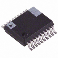
ADE7759ARSRL Analog Devices Inc, ADE7759ARSRL Datasheet - Page 21

ADE7759ARSRL
Manufacturer Part Number
ADE7759ARSRL
Description
IC ENERGY METERING 1PHASE 20SSOP
Manufacturer
Analog Devices Inc
Datasheet
1.ADE7759ARSZ.pdf
(36 pages)
Specifications of ADE7759ARSRL
Rohs Status
RoHS non-compliant
Input Impedance
390 KOhm
Measurement Error
0.1%
Voltage - I/o High
2.4V
Voltage - I/o Low
0.8V
Current - Supply
3mA
Voltage - Supply
4.75 V ~ 5.25 V
Operating Temperature
-40°C ~ 85°C
Mounting Type
Surface Mount
Package / Case
20-SSOP (0.200", 5.30mm Width)
Meter Type
Single Phase
For Use With
EVAL-ADE7759EBZ - BOARD EVALUATION FOR ADE7759
Figure 34 shows the signal processing chain for the active power
calculation in the ADE7759. As explained, the active power is
calculated by low pass filtering the instantaneous power signal.
Shown in Figure 35 is the maximum code (hexadecimal) output
range for the active power signal (LPF2) when the digital inte-
grator is disabled. Note that when the integrator is enabled, the
output range changes depending on the input signal frequency.
Furthermore, the output range can also be changed by the
active power gain register—see Channel 1 ADC section. The
minimum output range is given when the active power gain
register contents are equal to 800h, and the maximum range is
given by writing 7FFh to the active power gain register. This
can be used to calibrate the active power (or energy) calculation
in the ADE7759.
REV. A
1999Ah
CCCDh
00000h
V
I
VOLTAGE SIGNAL – v(t)
CURRENT SIGNAL – i(t)
VI
–12
–16
–20
–24
Figure 33. Frequency Response of LPF2
Figure 34. Active Power Signal Processing
–4
–8
0
1
Figure 32. Active Power Calculation
INSTANTANEOUS
POWER SIGNAL
CURRENT
i(t) = 2
MULTIPLIER
HPF
1
VOLTAGE
v(t) = 2
I
3
sin( t)
p(t) = V
V
FREQUENCY – Hz
1999Ah
1999Ah
INSTANTANEOUS POWER SIGNAL – p(t)
–40% TO +40% FS
sin( t)
20
00h
I – V
10
LPF2
I
cos(2 t)
CCCDh
ACTIVE POWER
ACTIVE REAL POWER
SIGNAL = V
SIGNAL – P
30
I
100
–21–
ENERGY CALCULATION
As stated earlier, power is defined as the rate of energy flow.
This relationship can be expressed mathematically as:
where P = power and E = energy.
Conversely, energy is given as the integral of power:
The AD7759 achieves the integration of the active power signal
by continuously accumulating the active power signal in the
40-bit active energy register (ASENERGY[39:0]). This discrete
time accumulation or summation is equivalent to integration in
continuous time. Equation 7 expresses this relationship:
where n is the discrete time sample number and T is the
sample period.
The discrete time sample period (T) for the accumulation regis-
ter in the ADE7759 is 1.1 µs (4/CLKIN). As well as calculating
the energy, this integration removes any sinusodial components
which may be in the active power signal.
Figure 36 shows a graphical representation of this discrete time
integration or accumulation. The active power signal in the wave-
form register is continuously added to the active energy register.
This addition is a signed addition; therefore negative energy will be
subtracted from the active energy contents.
As shown in Figure 36, the active power signal is accumulated
in a 40-bit signed register (AENERGY[39:0]). The active
power signal can be read from the waveform register by setting
MODE[14:13] = 0, 0 and setting the WSMP bit (Bit 3) in
the interrupt enable register to 1. Like Channel 1 and Channel 2
waveform sampling modes, the waveform data is available at
sample rates of 27.9 kSPS, 14 kSPS, 7 kSPS, or 3.5 kSPS—see
Figure 24. Figure 37 shows this energy accumulation for full-scale
signals (sinusodial) on analog inputs. The three curves displayed
illustrate the minimum period of time it takes the energy register to
roll over when the active power gain register contents are 7FFh,
000h, and 800h. The active power gain register is used to carry out
power calibration in the ADE7759. As shown, the fastest
integration time will occur when the active power gain register is
set to maximum full scale, i.e., 7FFh.
P
E
E
Figure 35. Active Power Calculation Output Range
=
= ∫
= ∫
dE
dt
Pdt
P t dt
ECCCDh
F999Ah
CCCDh
F3333h
13333h
00000h
( )
6666h
=
CHANNEL 1 (ACTIVE POWER)
CALIBRATION RANGE
Lim
T
000h
→
0
{APGAIN [11:0]}
n
∑
∞
=
0
7FFh
p nT
(
)
800h
×
T
+30% FS
–20% FS
+20% FS
+10% FS
–10% FS
–30% FS
ADE7759
POSITIVE
POWER
NEGATIVE
POWER
(5)
(6)
(7)


