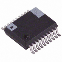
ADE7759ARSRL Analog Devices Inc, ADE7759ARSRL Datasheet - Page 32

ADE7759ARSRL
Manufacturer Part Number
ADE7759ARSRL
Description
IC ENERGY METERING 1PHASE 20SSOP
Manufacturer
Analog Devices Inc
Datasheet
1.ADE7759ARSZ.pdf
(36 pages)
Specifications of ADE7759ARSRL
Rohs Status
RoHS non-compliant
Input Impedance
390 KOhm
Measurement Error
0.1%
Voltage - I/o High
2.4V
Voltage - I/o Low
0.8V
Current - Supply
3mA
Voltage - Supply
4.75 V ~ 5.25 V
Operating Temperature
-40°C ~ 85°C
Mounting Type
Surface Mount
Package / Case
20-SSOP (0.200", 5.30mm Width)
Meter Type
Single Phase
For Use With
EVAL-ADE7759EBZ - BOARD EVALUATION FOR ADE7759
ADE7759
Interrupt Status Register (04H)/Reset Interrupt Status Register (05H)
The status register is used by the MCU to determine the source of an interrupt request (IRQ). When an interrupt event occurs in the
ADE7759, the corresponding flag in the interrupt status register is set logic high. If the enable bit for this flag is Logic 1 in the inter-
rupt enable register, the IRQ logic output goes active low. When the MCU services the interrupt, it must first carry out a read from
the interrupt status register to determine the source of the interrupt.
Bit
Location
0
1
2
3
4
5
6
7
(TEST MODE SELECTION SHOULD BE SET TO 0)
01 = CH1 + CH2 (40-BIT WAVEFORM SAMPLES)
(SHORT THE ANALOG INPUTS ON CHANNEL 2)
(SHORT THE ANALOG INPUTS ON CHANNEL 1)
(WAVEFORM SELECTION FOR SAMPLE MODE)
(WAVEFORM SAMPLES OUTPUT DATA RATE)
Table VII. Interrupt Status Register, Reset Interrupt Status Register, and Interrupt Enable Register
Interrupt
Flag
AEHF
SAG
CYCEND
WSMP
ZX
TEMP
RESET
AEOF
(SWAP CH1 AND CH2 ADCs)
00 = 27.9kSPS (CLKIN/128)
01 = 14.4kSPS (CLKIN/256)
11 = 3.6kSPS (CLKIN/1024)
10 = 7.2kSPS (CLKIN/512)
Description
Indicates that an interrupt was caused by the 0 to 1 transition of the MSB of the active energy register.
Indicates that an interrupt was caused by a SAG on the line voltage or no zero crossings were detected.
Indicates the end of energy accumulation over an integer number of half line cycles as defined by
the content of the LINECYC register—see Line Cycle Energy Accumulation Mode section.
Indicates that new data is present in the waveform register.
This status bit reflects the status of the ZX logic output—see Zero Crossing Detection section.
Indicates that a temperature conversion result is available in the temperature register.
Indicates the end of a reset (for both software or hardware reset). The corresponding enable bit has
no function in the interrupt enable register, i.e., this status bit is set at the end of a reset, but it
cannot be enabled to cause an interrupt.
Indicates that the active energy register has overflowed.
00 = LPF2
WAVSEL
10 = CH1
11 = CH2
DISCH2
DISCH1
TEST1
SWAP
DTRT
15 14 13 12 11 10
0
NOTE: REGISTER CONTENTS SHOW POWER-ON DEFAULTS
0
0
Figure 48. Mode Register
0
0
0
9
0
–32–
8
0
7
0
6
0
5
0
4
0
3
1
2
1
1
0
0
0
ADDR: 06H
DISHPF
(DISABLE HPF1 IN CHANNEL 1)
DISLPF2
(DISABLE LPF2 AFTER MULTIPLIER)
DISCF
(DISABLE FREQUENCY OUTPUT CF)
DISSAG
(DISABLE SAG OUTPUT)
ASUSPEND
(SUSPEND CH1 AND CH2 ADCs)
STEMP
(START TEMPERATURE SENSING)
SWRST
(SOFTWARE CHIP RESET)
CYCMODE
(LINE CYCLE ENERGY ACCUMULATION MODE)
REV. A


