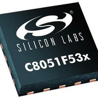
C8051F530-TB Silicon Laboratories Inc, C8051F530-TB Datasheet - Page 166

C8051F530-TB
Manufacturer Part Number
C8051F530-TB
Description
BOARD PROTOTYPE W/C8051F530
Manufacturer
Silicon Laboratories Inc
Type
MCUr
Datasheet
1.C8051F530-TB.pdf
(218 pages)
Specifications of C8051F530-TB
Contents
Board
Processor To Be Evaluated
C8051F52xA and C8051F53xA
Interface Type
USB
Lead Free Status / RoHS Status
Vendor undefined / Vendor undefined
For Use With/related Products
C8051F530
Lead Free Status / Rohs Status
Lead free / RoHS Compliant
- Current page: 166 of 218
- Download datasheet (2Mb)
C8051F52x/F52xA/F53x/F53xA
The following code programs the interface in Master mode, using the Enhanced Checksum and enables
the interface to operate at 19200 bits/sec using a 24 MHz system clock.
Table 17.2 includes the configuration values required for the typical system clocks and baud rates:
166
LINDATA = 0x0C;// Reset any error and the interrupt
SYSCLK
22.1184
11.0592
(MHz)
LIN0CF
LIN0CF
LINADDR
// Initialize the register (prescaler, multiplier and bit 8 of divider)
LINDATA
LINADDR
LINDATA
LINADDR
LINDATA
LINADDR
12.25
24.5
25
24
16
12
8
|= 0x80;// Initialize the checksum as Enhanced
0
0
0
0
0
0
0
0
0
|= 0x40;// Set the node as a Master
= 0x0D;// Point to the LIN0MUL register
= ( 0x01 << 6 ) + ( 0x00 << 1 ) + ( ( 0x13F & 0x0100 ) >> 8 );
= 0x0C;// Point to the LIN0DIV register
= (unsigned char)_0x13F;// Initialize LIN0DIV
= 0x0B;// Point to the LIN0SIZE register
= 0x08;// Point to LIN0CTRL register
= 0x80;// Activate the interface
20 K
1
1
1
1
1
0
0
0
0
Table 17.2. Manual Baud Rate Parameters Examples
312
306
300
276
200
306
300
276
200
0
0
0
0
0
0
0
0
0
19.2 K
1
1
1
1
1
0
0
0
0
325
319
312
288
208
319
312
288
208
Rev. 1.3
Baud (bits / sec)
1
1
1
1
1
1
1
1
1
9.6 K
1
1
1
1
1
0
0
0
0
325
319
312
288
208
319
312
288
208
3
3
3
3
3
3
3
3
3
4.8 K
1
1
1
1
1
0
0
0
0
325
319
312
288
208
319
312
288
208
19
19
19
19
19
19
19
19
19
1 K
1
1
1
1
1
0
0
0
0
312
306
300
276
200
306
300
276
200
Related parts for C8051F530-TB
Image
Part Number
Description
Manufacturer
Datasheet
Request
R
Part Number:
Description:
SMD/C°/SINGLE-ENDED OUTPUT SILICON OSCILLATOR
Manufacturer:
Silicon Laboratories Inc
Part Number:
Description:
Manufacturer:
Silicon Laboratories Inc
Datasheet:
Part Number:
Description:
N/A N/A/SI4010 AES KEYFOB DEMO WITH LCD RX
Manufacturer:
Silicon Laboratories Inc
Datasheet:
Part Number:
Description:
N/A N/A/SI4010 SIMPLIFIED KEY FOB DEMO WITH LED RX
Manufacturer:
Silicon Laboratories Inc
Datasheet:
Part Number:
Description:
N/A/-40 TO 85 OC/EZLINK MODULE; F930/4432 HIGH BAND (REV E/B1)
Manufacturer:
Silicon Laboratories Inc
Part Number:
Description:
EZLink Module; F930/4432 Low Band (rev e/B1)
Manufacturer:
Silicon Laboratories Inc
Part Number:
Description:
I°/4460 10 DBM RADIO TEST CARD 434 MHZ
Manufacturer:
Silicon Laboratories Inc
Part Number:
Description:
I°/4461 14 DBM RADIO TEST CARD 868 MHZ
Manufacturer:
Silicon Laboratories Inc
Part Number:
Description:
I°/4463 20 DBM RFSWITCH RADIO TEST CARD 460 MHZ
Manufacturer:
Silicon Laboratories Inc
Part Number:
Description:
I°/4463 20 DBM RADIO TEST CARD 868 MHZ
Manufacturer:
Silicon Laboratories Inc
Part Number:
Description:
I°/4463 27 DBM RADIO TEST CARD 868 MHZ
Manufacturer:
Silicon Laboratories Inc
Part Number:
Description:
I°/4463 SKYWORKS 30 DBM RADIO TEST CARD 915 MHZ
Manufacturer:
Silicon Laboratories Inc
Part Number:
Description:
N/A N/A/-40 TO 85 OC/4463 RFMD 30 DBM RADIO TEST CARD 915 MHZ
Manufacturer:
Silicon Laboratories Inc
Part Number:
Description:
I°/4463 20 DBM RADIO TEST CARD 169 MHZ
Manufacturer:
Silicon Laboratories Inc


