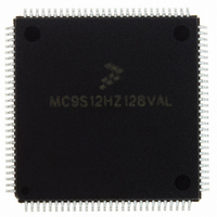
MC9S12HZ128VAL Freescale Semiconductor, MC9S12HZ128VAL Datasheet - Page 265

MC9S12HZ128VAL
Manufacturer Part Number
MC9S12HZ128VAL
Description
IC MCU 16BIT 2K FLASH 112-LQFP
Manufacturer
Freescale Semiconductor
Series
HCS12r
Datasheet
1.MC9S12HZ128CAL.pdf
(692 pages)
Specifications of MC9S12HZ128VAL
Core Processor
HCS12
Core Size
16-Bit
Speed
25MHz
Connectivity
CAN, EBI/EMI, I²C, SCI, SPI
Peripherals
LCD, Motor control PWM, POR, PWM, WDT
Number Of I /o
85
Program Memory Size
128KB (128K x 8)
Program Memory Type
FLASH
Eeprom Size
2K x 8
Ram Size
6K x 8
Voltage - Supply (vcc/vdd)
2.35 V ~ 5.5 V
Data Converters
A/D 16x10b
Oscillator Type
Internal
Operating Temperature
-40°C ~ 105°C
Package / Case
112-LQFP
Processor Series
S12H
Core
HCS12
Data Bus Width
16 bit
Data Ram Size
6 KB
Interface Type
I2C/SCI/SPI
Maximum Clock Frequency
50 MHz
Number Of Programmable I/os
85
Number Of Timers
8
Maximum Operating Temperature
+ 105 C
Mounting Style
SMD/SMT
3rd Party Development Tools
EWHCS12
Minimum Operating Temperature
- 40 C
On-chip Adc
16-ch x 10-bit
Lead Free Status / RoHS Status
Lead free / RoHS Compliant
Available stocks
Company
Part Number
Manufacturer
Quantity
Price
Company:
Part Number:
MC9S12HZ128VAL
Manufacturer:
Freescale Semiconductor
Quantity:
10 000
Part Number:
MC9S12HZ128VAL
Manufacturer:
FREESCALE
Quantity:
20 000
- Current page: 265 of 692
- Download datasheet (4Mb)
9.3.2
9.3.2.1
This register controls the operating mode of the motor controller module.
Freescale Semiconductor
MCPRE[1:0]
MCSWAI
Reset
MCTOIF
FAST
Field
DITH
6:5
4
3
2
0
W
R
1
Write accesses to “Reserved” addresses have no effect. Read accesses to “Reserved” addresses provide
invalid data (0x0000).
0x003E
0x003F
Offset
Register Descriptions
Motor Controller Module Stop in Wait Mode
0 Entering wait mode has no effect on the motor controller module and the associated port pins maintain the
1 Entering wait mode will stop the clock of the module and debias the analog circuitry. The
0 PWM operates in 11-bit resolution mode, duty cycle registers of all channels are switched to word mode.
1 PWM operates in 7-bit resolution (fast) mode, duty cycle registers of all channels are switched to byte mode.
0 Dither feature is disabled.
1 Dither feature is enabled.
0 A motor controller timer counter overflow has not occurred since the last reset or since the bit was cleared.
1 A motor controller timer counter overflow has occurred.
Motor Controller Prescaler Select — MCPRE1 and MCPRE0 determine the prescaler value that sets the
Motor Controller PWM Resolution Mode
Motor Control/Driver Dither Feature Enable (refer to
Motor Controller Timer Counter Overflow Interrupt Flag — This bit is set when a motor controller timer
Motor Controller Control Register 0
7
0
0
functionality they had prior to entering wait mode both during wait mode and after exiting wait mode.
motor controller timer counter clock frequency (f
clock (f
frequency f
possible combinations of MCPRE1 and MCPRE0
module will release the pins.
counter overflow occurs. The bit is cleared by writing a 1 to the bit.
Reserved
Reserved
= Unimplemented or Reserved
BUS
) as shown in
Figure 9-3. Motor Controller Control Register 0 (MCCTL0)
TC
6
0
until the start of the next PWM period.
MCPRE[1:0]
Figure 9-2. MC10B8C Memory Map (continued)
Table 9-2. MCCTL0 Field Descriptions
Figure
MC9S12HZ256 Data Sheet, Rev. 2.05
5
0
9-22. Writes to MCPRE1 or MCPRE0 will not affect the timer counter clock
MCSWAI
Register
4
0
Description
TC
). The clock source for the prescaler is the peripheral bus
Table 9-3
Section 9.4.1.3.5, “Dither Bit
FAST
3
0
shows the prescaler values that result from the
Chapter 9 Motor Controller (MC10B8CV1)
DITH
2
0
(DITH)”)
1
0
0
Access
—
—
MCTOIF
0
0
265
Related parts for MC9S12HZ128VAL
Image
Part Number
Description
Manufacturer
Datasheet
Request
R
Part Number:
Description:
Manufacturer:
Freescale Semiconductor, Inc
Datasheet:
Part Number:
Description:
Manufacturer:
Freescale Semiconductor, Inc
Datasheet:
Part Number:
Description:
Manufacturer:
Freescale Semiconductor, Inc
Datasheet:
Part Number:
Description:
Manufacturer:
Freescale Semiconductor, Inc
Datasheet:
Part Number:
Description:
Manufacturer:
Freescale Semiconductor, Inc
Datasheet:
Part Number:
Description:
Manufacturer:
Freescale Semiconductor, Inc
Datasheet:
Part Number:
Description:
Manufacturer:
Freescale Semiconductor, Inc
Datasheet:
Part Number:
Description:
Manufacturer:
Freescale Semiconductor, Inc
Datasheet:
Part Number:
Description:
Manufacturer:
Freescale Semiconductor, Inc
Datasheet:
Part Number:
Description:
Manufacturer:
Freescale Semiconductor, Inc
Datasheet:
Part Number:
Description:
Manufacturer:
Freescale Semiconductor, Inc
Datasheet:
Part Number:
Description:
Manufacturer:
Freescale Semiconductor, Inc
Datasheet:
Part Number:
Description:
Manufacturer:
Freescale Semiconductor, Inc
Datasheet:
Part Number:
Description:
Manufacturer:
Freescale Semiconductor, Inc
Datasheet:
Part Number:
Description:
Manufacturer:
Freescale Semiconductor, Inc
Datasheet:


