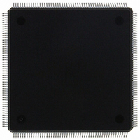
MCF5307AI90B Freescale Semiconductor, MCF5307AI90B Datasheet - Page 317

MCF5307AI90B
Manufacturer Part Number
MCF5307AI90B
Description
IC MPU 32BIT COLDF 90MHZ 208FQFP
Manufacturer
Freescale Semiconductor
Series
MCF530xr
Datasheets
1.MCF5307AI66B.pdf
(484 pages)
2.MCF5307AI66B.pdf
(16 pages)
3.MCF5307AI66B.pdf
(2 pages)
Specifications of MCF5307AI90B
Core Processor
Coldfire V3
Core Size
32-Bit
Speed
90MHz
Connectivity
EBI/EMI, I²C, UART/USART
Peripherals
DMA, POR, WDT
Number Of I /o
16
Program Memory Type
ROMless
Ram Size
4K x 8
Voltage - Supply (vcc/vdd)
3 V ~ 3.6 V
Oscillator Type
External
Operating Temperature
0°C ~ 70°C
Package / Case
208-FQFP
Maximum Clock Frequency
90 MHz
Maximum Operating Temperature
+ 105 C
Mounting Style
SMD/SMT
Minimum Operating Temperature
0 C
Family Name
MCF5xxx
Device Core
ColdFire
Device Core Size
32b
Frequency (max)
90MHz
Instruction Set Architecture
RISC
Supply Voltage 1 (typ)
3.3V
Operating Temp Range
0C to 70C
Operating Temperature Classification
Commercial
Mounting
Surface Mount
Pin Count
208
Package Type
FQFP
Program Memory Size
8KB
Cpu Speed
90MHz
Embedded Interface Type
I2C, UART
Digital Ic Case Style
FQFP
No. Of Pins
208
Supply Voltage Range
3V To 3.6V
Rohs Compliant
Yes
Lead Free Status / RoHS Status
Lead free / RoHS Compliant
Eeprom Size
-
Program Memory Size
-
Data Converters
-
Lead Free Status / Rohs Status
Lead free / RoHS Compliant
Available stocks
Company
Part Number
Manufacturer
Quantity
Price
Company:
Part Number:
MCF5307AI90B
Manufacturer:
FREESCAL
Quantity:
153
Company:
Part Number:
MCF5307AI90B
Manufacturer:
Freescale Semiconductor
Quantity:
10 000
Part Number:
MCF5307AI90B
Manufacturer:
FREESCALE
Quantity:
20 000
- Current page: 317 of 484
- Download datasheet (6Mb)
14.3.3 UART Status Registers (USRn)
The USRn, Figure 14-4, shows status of the transmitter, the receiver, and the FIFO.
Table 14-4 describes USRn fields.
Bits
3–0
Bits
Address
7
6
Reset
Field
R/W
Name
SB
Name
RB
FE
Stop-bit length control. Selects the length of the stop bit appended to the transmitted character.
Stop-bit lengths of 9/16th to 2 bits are programmable for 6–8 bit characters. Lengths of 1 1/16th to 2
bits are programmable for 5-bit characters. In all cases, the receiver checks only for a high condition at
the center of the first stop-bit position, that is, one bit time after the last data bit or after the parity bit, if
parity is enabled. If an external 1x clock is used for the transmitter, clearing bit 3 selects one stop bit
and setting bit 3 selects 2 stop bits for transmission.
RB
7
Received break. The received break circuit detects breaks that originate in the middle of a received
character. However, a break in the middle of a character must persist until the end of the next
detected character time.
0 No break was received.
1 An all-zero character of the programmed length was received without a stop bit. RB is valid only
Framing error.
0 No framing error occurred.
1 No stop bit was detected when the corresponding data character in the FIFO was received. The
0000 1.063
0001 1.125
0010 1.188
0011 1.250
SB
when RxRDY = 1. Only a single FIFO position is occupied when a break is received. Further
entries to the FIFO are inhibited until RxD returns to the high state for at least one-half bit time,
which is equal to two successive edges of the UART clock.
stop-bit check occurs in the middle of the first stop-bit position. FE is valid only when RxRDY = 1.
Table 14-3. UMR2n Field Descriptions (Continued)
5 Bits
Figure 14-4. UART Status Register (USRn)
FE
6
Freescale Semiconductor, Inc.
Table 14-4. USRn Field Descriptions
For More Information On This Product,
6–8 Bits
0.563
0.625
0.688
0.750
Chapter 14. UART Modules
PE
5
Go to: www.freescale.com
MBAR + 0x1C4 (USR0), 0x204 (USR1)
0100
0101
0110
0111
SB
5 Bits
1.313
1.375
1.438
1.500
OE
4
0000_0000
Read only
Description
Description
6–8 Bits
0.813
0.875
0.938
1.000
TxEMP
3
1000
1001
1010
1011
SB
TxRDY
2
5–8 Bits
1.563
1.625
1.688
1.750
Register Descriptions
FFULL
1100
1101
1110
1111
1
SB
5–8 Bits
1.813
1.875
1.938
2.000
RxRDY
0
14-7
Related parts for MCF5307AI90B
Image
Part Number
Description
Manufacturer
Datasheet
Request
R
Part Number:
Description:
Manufacturer:
Freescale Semiconductor, Inc
Datasheet:
Part Number:
Description:
Mcf5307 Coldfire Integrated Microprocessor User
Manufacturer:
Freescale Semiconductor, Inc
Datasheet:
Part Number:
Description:
Manufacturer:
Freescale Semiconductor, Inc
Datasheet:
Part Number:
Description:
Manufacturer:
Freescale Semiconductor, Inc
Datasheet:
Part Number:
Description:
Manufacturer:
Freescale Semiconductor, Inc
Datasheet:
Part Number:
Description:
Manufacturer:
Freescale Semiconductor, Inc
Datasheet:
Part Number:
Description:
Manufacturer:
Freescale Semiconductor, Inc
Datasheet:
Part Number:
Description:
Manufacturer:
Freescale Semiconductor, Inc
Datasheet:
Part Number:
Description:
Manufacturer:
Freescale Semiconductor, Inc
Datasheet:
Part Number:
Description:
Manufacturer:
Freescale Semiconductor, Inc
Datasheet:
Part Number:
Description:
Manufacturer:
Freescale Semiconductor, Inc
Datasheet:
Part Number:
Description:
Manufacturer:
Freescale Semiconductor, Inc
Datasheet:
Part Number:
Description:
Manufacturer:
Freescale Semiconductor, Inc
Datasheet:
Part Number:
Description:
Manufacturer:
Freescale Semiconductor, Inc
Datasheet:
Part Number:
Description:
Manufacturer:
Freescale Semiconductor, Inc
Datasheet:


