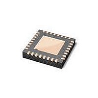
LPC1113FHN33/302,5 NXP Semiconductors, LPC1113FHN33/302,5 Datasheet - Page 25

LPC1113FHN33/302,5
Manufacturer Part Number
LPC1113FHN33/302,5
Description
IC MCU LV 32BIT 24K FLAS 32VQFN
Manufacturer
NXP Semiconductors
Series
LPC1100Lr
Datasheet
1.LPC1114FHN333015.pdf
(66 pages)
Specifications of LPC1113FHN33/302,5
Featured Product
LPC1100L 32-Bit MCU
Core Processor
ARM Cortex-M0
Core Size
32-Bit
Speed
50MHz
Connectivity
I²C, SPI, UART/USART
Peripherals
Brown-out Detect/Reset, POR, WDT
Number Of I /o
28
Program Memory Size
24KB (24K x 8)
Program Memory Type
FLASH
Ram Size
8K x 8
Voltage - Supply (vcc/vdd)
1.8 V ~ 3.6 V
Data Converters
A/D 8x10b
Oscillator Type
Internal
Operating Temperature
-40°C ~ 85°C
Package / Case
32-VQFN Exposed Pad
Processor Series
LPC1113
Core
ARM Cortex-M0
Data Bus Width
32 bit
Data Ram Size
8 KB
Interface Type
I2C, UART, SPI, SSP
Maximum Clock Frequency
50 MHz
Number Of Programmable I/os
42
Number Of Timers
4
Maximum Operating Temperature
+ 85 C
Mounting Style
SMD/SMT
Lead Free Status / RoHS Status
Lead free / RoHS Compliant
Eeprom Size
-
Lead Free Status / Rohs Status
Details
Other names
568-5148
NXP Semiconductors
LPC1111_12_13_14
Product data sheet
7.14.1 Features
7.13 System tick timer
7.14 Watchdog timer
The ARM Cortex-M0 includes a system tick timer (SYSTICK) that is intended to generate
a dedicated SYSTICK exception at a fixed time interval (typically 10 ms).
The purpose of the watchdog is to reset the microcontroller within a selectable time
period.
•
•
•
•
•
•
•
•
•
•
•
•
Counter or timer operation.
One capture channel per timer, that can take a snapshot of the timer value when an
input signal transitions. A capture event may also generate an interrupt.
Four match registers per timer that allow:
– Continuous operation with optional interrupt generation on match.
– Stop timer on match with optional interrupt generation.
– Reset timer on match with optional interrupt generation.
Up to four external outputs corresponding to match registers, with the following
capabilities:
– Set LOW on match.
– Set HIGH on match.
– Toggle on match.
– Do nothing on match.
Internally resets chip if not periodically reloaded.
Debug mode.
Enabled by software but requires a hardware reset or a watchdog reset/interrupt to be
disabled.
Incorrect/Incomplete feed sequence causes reset/interrupt if enabled.
Flag to indicate watchdog reset.
Programmable 24-bit timer with internal prescaler.
Selectable time period from (T
multiples of T
The Watchdog Clock (WDCLK) source can be selected from the Internal RC oscillator
(IRC), the Watchdog oscillator, or the main clock. This gives a wide range of potential
timing choices of Watchdog operation under different power reduction conditions. It
also provides the ability to run the WDT from an entirely internal source that is not
dependent on an external crystal and its associated components and wiring for
increased reliability.
All information provided in this document is subject to legal disclaimers.
cy(WDCLK)
Rev. 4 — 10 February 2011
× 4.
cy(WDCLK)
× 256 × 4) to (T
32-bit ARM Cortex-M0 microcontroller
LPC1111/12/13/14
cy(WDCLK)
× 2
© NXP B.V. 2011. All rights reserved.
24
× 4) in
25 of 66


