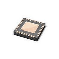
LPC1113FHN33/302,5 NXP Semiconductors, LPC1113FHN33/302,5 Datasheet - Page 32

LPC1113FHN33/302,5
Manufacturer Part Number
LPC1113FHN33/302,5
Description
IC MCU LV 32BIT 24K FLAS 32VQFN
Manufacturer
NXP Semiconductors
Series
LPC1100Lr
Datasheet
1.LPC1114FHN333015.pdf
(66 pages)
Specifications of LPC1113FHN33/302,5
Featured Product
LPC1100L 32-Bit MCU
Core Processor
ARM Cortex-M0
Core Size
32-Bit
Speed
50MHz
Connectivity
I²C, SPI, UART/USART
Peripherals
Brown-out Detect/Reset, POR, WDT
Number Of I /o
28
Program Memory Size
24KB (24K x 8)
Program Memory Type
FLASH
Ram Size
8K x 8
Voltage - Supply (vcc/vdd)
1.8 V ~ 3.6 V
Data Converters
A/D 8x10b
Oscillator Type
Internal
Operating Temperature
-40°C ~ 85°C
Package / Case
32-VQFN Exposed Pad
Processor Series
LPC1113
Core
ARM Cortex-M0
Data Bus Width
32 bit
Data Ram Size
8 KB
Interface Type
I2C, UART, SPI, SSP
Maximum Clock Frequency
50 MHz
Number Of Programmable I/os
42
Number Of Timers
4
Maximum Operating Temperature
+ 85 C
Mounting Style
SMD/SMT
Lead Free Status / RoHS Status
Lead free / RoHS Compliant
Eeprom Size
-
Lead Free Status / Rohs Status
Details
Other names
568-5148
NXP Semiconductors
9. Static characteristics
Table 7.
T
LPC1111_12_13_14
Product data sheet
Symbol
V
LPC1100 series (LPC111x/101/201/301) power consumption
I
LPC1100L series (LPC111x/102/202/302) power consumption in low-current mode
I
Standard port pins, RESET
I
I
I
DD
DD
IL
IH
OZ
amb
DD
= −40 °C to +85 °C, unless otherwise specified.
Static characteristics
Parameter
supply voltage (core
and external rail)
supply current
supply current
LOW-level input current V
HIGH-level input
current
OFF-state output
current
All information provided in this document is subject to legal disclaimers.
Conditions
Active mode; code
executed from flash
Sleep mode;
Deep-sleep mode;
V
Deep power-down mode;
V
Active mode; code
executed from flash
Sleep mode;
Deep-sleep mode;
V
Deep power-down mode;
V
resistor disabled
V
pull-down resistor
disabled
V
on-chip pull-up/down
resistors disabled
DD
DD
DD
DD
I
I
O
system clock = 12 MHz
system clock = 50 MHz
system clock = 12 MHz
system clock = 12 MHz
system clock = 50 MHz
system clock = 12 MHz
= 0 V; on-chip pull-up
= V
= 0 V; V
while(1){}
V
V
V
= 3.3 V
= 3.3 V
while(1){}
V
V
V
= 3.3 V
= 3.3 V
DD
DD
DD
DD
DD
DD
DD
Rev. 4 — 10 February 2011
; on-chip
= 3.3 V
= 3.3 V
= 3.3 V
= 3.3 V
= 3.3 V
= 3.3 V
O
= V
DD
;
[2][3][4]
[2][3][5]
[2][3][4]
[2][3][8]
[2][3][4]
[2][3][5]
[2][3][4]
[2][3][8]
[5][6]
[6][7]
[5][6]
[2][9]
[5][6]
[6][7]
[5][6]
[2][9]
32-bit ARM Cortex-M0 microcontroller
Min
1.8
-
-
-
-
-
-
-
-
-
-
-
-
-
LPC1111/12/13/14
[10]
Typ
3.3
3
9
2
6
220
2
7
1
2
220
0.5
0.5
0.5
[1]
© NXP B.V. 2011. All rights reserved.
Max
3.6
-
-
-
-
-
-
-
-
-
-
10
10
10
32 of 66
Unit
V
mA
mA
mA
μA
nA
mA
mA
mA
μA
nA
nA
nA
nA


