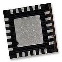
IMU-3000 INVENSENSE, IMU-3000 Datasheet - Page 14

IMU-3000
Manufacturer Part Number
IMU-3000
Description
GYRO, TRI-AXIS, PROG +/-2000 DEG/S
Manufacturer
INVENSENSE
Datasheet
1.IMU-3000.pdf
(56 pages)
Specifications of IMU-3000
No. Of Axes
3
Sensor Case Style
QFN
No. Of Pins
24
Supply Voltage Range
2.1V To 3.6V
Operating Temperature Range
-40°C To +85°C
Interface
I2C, Serial
Interface Type
I2C, Serial
Rohs Compliant
Yes
Lead Free Status / RoHS Status
Lead free / RoHS Compliant
4
4.1
Applications Information
Pin Out and Signal Description
2, 3, 4, 5, 14,
Pin Number
15, 16, 17
10
11
12
13
18
19
20
21
22
23
24
1
6
7
8
9
Pin Name
REGOUT
AUX_DA
CLKOUT
AUX_CL
RESV-G
VLOGIC
CPOUT
CLKIN
RESV
RESV
GND
VDD
AD0
SCL
SDA
INT
NC
IMU-3000 Product Specification
Pin Description
External reference clock input
Interface to a 3
either VDD or VLOGIC. See Section 7 for more details.
Interface to a 3
either VDD or VLOGIC. See Section 7 for more details.
Digital I/O supply voltage. VLOGIC must be ≤ VDD at all times.
I
Regulator filter capacitor connection
Reserved – Connect to Ground.
Interrupt digital output (totem pole or open-drain)
Power supply voltage and Digital I/O supply voltage
Power supply ground
Reserved. Do not connect.
Charge pump capacitor connection
Reserved. Do not connect.
1MHz clock output for third-party accelerometer synchronization
I
I
Not internally connected. May be used for PCB trace routing.
2
2
2
C Slave Address LSB
C serial clock
C serial data
14 of 56
rd
rd
party accelerometer, SDA pin. Logic levels are set to be
party accelerometer, SCL pin. Logic levels are set to be
Document Number: PS-IMU-3000A-00-01.1
Revision: 1.1
Release Date: 08/19/2010


