IMU-3000 INVENSENSE, IMU-3000 Datasheet - Page 46
IMU-3000
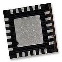
Manufacturer Part Number
IMU-3000
Description
GYRO, TRI-AXIS, PROG +/-2000 DEG/S
Manufacturer
INVENSENSE
Datasheet
1.IMU-3000.pdf
(56 pages)
Specifications of IMU-3000
No. Of Axes
3
Sensor Case Style
QFN
No. Of Pins
24
Supply Voltage Range
2.1V To 3.6V
Operating Temperature Range
-40°C To +85°C
Interface
I2C, Serial
Interface Type
I2C, Serial
Rohs Compliant
Yes
Lead Free Status / RoHS Status
Lead free / RoHS Compliant


InvenSense MEMS Gyros sense rate of rotation. In addition, gyroscopes sense mechanical stress coming
from the PCB. This PCB stress is minimized with simple design rules:
1. Component Placement – Testing indicates that there are no specific design considerations other than
2. The area below the MEMS gyro (on the same side of the board) must be defined as a keep-out area. It is
3. Traces connected to pads should be as much symmetric as possible. Symmetry and balance for pad
4. Testing indicates that 3-Volt peak-to-peak signals run under the gyro package or directly on top of the
5. To achieve best performance over temperature and to prevent thermo-mechanical package stress, do
11.2.3 Exposed Die Pad Precautions
The IMU-3000 has very low active and standby current consumption. The exposed die pad is not required for
heat sinking, and should not be soldered to the PCB since soldering to it contributes to performance changes
due to package thermo-mechanical stress. There is no electrical connection between the pad and the die.
11.2.4 Gyro Removal from PCB
Never apply high mechanical force while removing MEMS gyros from PCB. Otherwise, the QFN package
leads can be removed and failure analysis of the gyro unit will be impossible. Tweezers are practical.
Do not apply a pulling force upward. Instead apply a gentle force sideward while heating. When sufficient
heat has been applied, the unit will start to slide sideways and can now be pulled gently upwards with the
tweezers.
In any case, mechanical or thermo-mechanical overstress during manual handling and soldering, (especially
contact between the soldering iron or hot air gun and the package) has to be avoided.
If safe removal of the suspected component is not possible or deemed too risky, send the whole PCB or the
part of the PCB containing the defective component back to InvenSense. If requested, we will return the PCB
after we have removed the gyro.
11.3
Testing indicates that 3-Volt peak-to-peak signals run under the gyro package or directly on top of the
package of frequencies from DC to 1MHz do not affect the operation of the MEMS gyro. However, routing
traces or vias under the MEMS gyro package such that they run under the exposed die pad is prohibited.
11.4
Do not place large insertion components such as keyboard or similar buttons, connectors, or shielding boxes
at a distance of less than 6 mm from the MEMS gyro. Maintain generally accepted industry design practices
for component placement near the IMU-3000 to prevent noise coupling and thermo-mechanical stress.
generally accepted industry design practices for component placement near the IMU-3000 gyroscope to
prevent noise coupling and thermo-mechanical stress.
strongly recommended to not place any structure in top metal layer underneath the keep-out area.
connection will help component self alignment and will lead to better control of solder paste reduction
after reflow.
package of frequencies from DC to 1MHz do not affect the operation of the MEMS gyro. However,
routing traces or vias under the MEMS gyro package such that they run under the exposed die pad is
prohibited.
not place large insertion components like buttons, connectors, or shielding boxes at a distance of less
than 6 mm from the MEMS gyro.
Trace Routing
Component Placement
IMU-3000 Product Specification
46 of 56
Document Number: PS-IMU-3000A-00-01.1
Revision: 1.1
Release Date: 08/19/2010
Related parts for IMU-3000
Image
Part Number
Description
Manufacturer
Datasheet
Request
R

Part Number:
Description:
GYRO, DUAL (X+Y) AXIS, +/-500 DEG/S
Manufacturer:
INVENSENSE
Datasheet:
Part Number:
Description:
GYRO, DUAL (X+Y) AXIS, +/-2000 DEG/S
Manufacturer:
INVENSENSE
Datasheet:
Part Number:
Description:
GYRO, SINGLE (Z) AXIS, +/-500 DEG/S
Manufacturer:
INVENSENSE
Datasheet:
Part Number:
Description:
GYRO, SINGLE (Z) AXIS, +/-2000 DEG/S
Manufacturer:
INVENSENSE
Datasheet:

Part Number:
Description:
IC, GYRO, TRI-AXIS, +/-2000 DEG/S
Manufacturer:
INVENSENSE
Datasheet:
Part Number:
Description:
IC, GYRO/ACCEL, 9-AXIS FUSION, PROG
Manufacturer:
INVENSENSE
Datasheet:
Part Number:
Description:
GYRO/ACCEL, 9-AXIS FUSION, PROG, I2C
Manufacturer:
INVENSENSE
Datasheet:
Part Number:
Description:
IC, GYRO/ACCEL, 9-AXIS FUSION, PROG
Manufacturer:
INVENSENSE
Datasheet:
Part Number:
Description:
GYRO/ACCEL, 9-AXIS FUSION, PROG, I2C
Manufacturer:
INVENSENSE
Datasheet: