IMU-3000 INVENSENSE, IMU-3000 Datasheet - Page 36

IMU-3000
Manufacturer Part Number
IMU-3000
Description
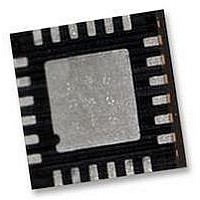
GYRO, TRI-AXIS, PROG +/-2000 DEG/S
Manufacturer
INVENSENSE
Datasheet
1.IMU-3000.pdf
(56 pages)
Specifications of IMU-3000
No. Of Axes
3
Sensor Case Style
QFN
No. Of Pins
24
Supply Voltage Range
2.1V To 3.6V
Operating Temperature Range
-40°C To +85°C
Interface
I2C, Serial
Interface Type
I2C, Serial
Rohs Compliant
Yes
Lead Free Status / RoHS Status
Lead free / RoHS Compliant
10.10 Register 26 – Interrupt Status
Type: Read only
Description:
This register is used to determine the status of the IMU-3000 interrupt. Whenever one of the
interrupt sources is triggered, the corresponding bit will be set. The polarity of the interrupt pin
(active high/low) and the latch type (pulse or latch) has no affect on these status bits.
In normal use, the RAW_DATA_RDY interrupt is used to determine when new sensor data is
available in either the sensor registers (27 to 34) or in the FIFO (60).
Interrupt Status bits get cleared as determined by INT_ANYRD_2CLEAR in the interrupt
configuration register (23).
Parameters:
FIFO_FULL
I2C_MST_ERR
IMU_RDY
DMP_DONE
RAW_DATA_RDY Raw data or FIFO data is ready
Register
(Hex)
1A
(Decimal)
Register
26
FIFO has overflowed. Cleared when Register 26 is read and when FIFO_RST
(register 61) is set.
The IMU-3000 did not receive an acknowledge from the accelerometer on the
secondary I
PLL ready
Digital Motion Processor (DMP) is done
FIFO_FULL
IMU-3000 Product Specification
Bit7
2
C bus when the IMU-3000 was acting as a master
Bit6
-
36 of 56
Bit5
-
Bit4
-
I2C_MST
_ERR
Bit3
Document Number: PS-IMU-3000A-00-01.1
Revision: 1.1
Release Date: 08/19/2010
IMU_
RDY
Bit2
DONE
DMP_
Bit1
DATA_
RAW_
RDY
Bit0
Default
Value
00h


