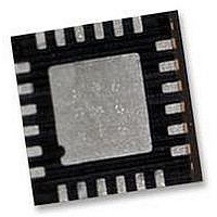
IMU-3000 INVENSENSE, IMU-3000 Datasheet - Page 39

IMU-3000
Manufacturer Part Number
IMU-3000
Description
GYRO, TRI-AXIS, PROG +/-2000 DEG/S
Manufacturer
INVENSENSE
Datasheet
1.IMU-3000.pdf
(56 pages)
Specifications of IMU-3000
No. Of Axes
3
Sensor Case Style
QFN
No. Of Pins
24
Supply Voltage Range
2.1V To 3.6V
Operating Temperature Range
-40°C To +85°C
Interface
I2C, Serial
Interface Type
I2C, Serial
Rohs Compliant
Yes
Lead Free Status / RoHS Status
Lead free / RoHS Compliant
10.14 Register 60 – FIFO Data
Type: Read only
Parameters:
FIFO_DATA
Description:
This is the output register of the FIFO. Each read of this register gets the oldest contents of the IMU-
3000 FIFO buffer; thus the data is read out in the same order that the IMU-3000 put the data in. If
the FIFO operation is enabled, the IMU-3000 puts new data into the FIFO at each sample interval.
The data that goes in is determined by the FIFO enable register (18).
A burst read or write is required for reading or writing multiple bytes to or from this register, since any
read or write on this register causes an auto increment and a prefetch to occur.
Proper operation of the FIFO requires that at least one word (2 bytes) of data be left in the FIFO
during any read operation. To implement this, it is recommended that one extra two byte word
(FIFO_FOOTER) be added to the end of the FIFO data so that all desired data can be read at each
cycle, leaving the extra word remaining in the FIFO. This extra word will be read out (first) during the
next read operation on the FIFO.
Data is read into the FIFO in the following order:
For example, if it is desired to obtain temperature, gyro, and accelerometer data from the FIFO, then
one should also add FIFO_FOOTER into the FIFO enable register (18) in addition to the desired
data. As shown in the figure below, the first time data is written to the FIFO, the FIFO will contain:
TEMP_OUT, GYRO_XOUT, GYRO_YOUT, GYRO_ZOUT, AUX_XOUT, AUX_YOUT, AUX_ZOUT,
and FIFO_FOOTER. The first FIFO read will read all but the FIFO_FOOTER data, which will be
read in the 2
previous read is read out first, followed by all but the last FIFO_FOOTER data in the FIFO. This
pattern of reading is continued, as shown in the figure.
Note that the first FIFO read is similar to the subsequent reads in that one word of data is always left
in the FIFO. It differs, though, in that the in subsequent reads the leftover data from the previous
read is read first; however, for the first read there is no leftover data from a previous read.
If the FIFO is allowed to overflow, it operates as a circular buffer in which at any time it contains the
most recent 512 bytes. Recommended operation in this mode is to disable data going into the FIFO
prior to reading the FIFO to avoid pointer conflicts. After halting the FIFO input, the 512 bytes in the
FIFO should be read out in a single burst read. The first byte read will not be valid.
Register
(Hex)
3C
TEMP_OUT
GYRO_XOUT
GYRO_YOUT
GYRO_ZOUT
AUX_XOUT
AUX_YOUT
AUX_ZOUT
FIFO_FOOTER
(Decimal)
Register
nd
60
FIFO read. In the 2
Contains the FIFO data
IMU-3000 Product Specification
Bit7
Temperature high and low bytes (2 bytes)
X Gyro high and low bytes (2 bytes)
Y Gyro high and low bytes (2 bytes)
Z Gyro high and low bytes (2 bytes)
X Accelerometer high and low bytes (2 bytes)
Y Accelerometer high and low bytes (2 bytes)
Z Accelerometer high and low bytes (2 bytes)
Last word for FIFO read (2 bytes)
Bit6
nd
FIFO read, the FIFO_FOOTER data that was left over from the
39 of 56
Bit5
Bit4
FIFO_DATA
Bit3
Document Number: PS-IMU-3000A-00-01.1
Revision: 1.1
Release Date: 08/19/2010
Bit2
Bit1
Bit0
Default
Value
00h


